Engine intake manifold

An intake manifold and engine technology, applied in engine components, engine control, combustion engine, etc., can solve the problems of increased manufacturing difficulty, poor emission, large intake resistance, etc., to improve the mixing of oil and gas and reduce the flow energy Loss, the effect of small air intake resistance

Active Publication Date: 2013-03-06
GREAT WALL MOTOR CO LTD
View PDF4 Cites 1 Cited by
  • Summary
  • Abstract
  • Description
  • Claims
  • Application Information

AI Technical Summary

Problems solved by technology

The disadvantage of the traditional intake manifold is that the airflow entering each cylinder of the engine is not uniform, so that the size of the vortex generated by each cylinder is different, resulting in different combustion conditions of each cylinder, causing combustion deterioration and emission deterioration
Especially the intake manifold made of cast aluminum alloy, due to its complex structure and high mass, not only increases the difficulty of manufacture, but also does not meet the design requirements of lightweight; moreover, the inner cavity of the intake manifold is not smooth, resulting in large intake resistance , Inflatable efficiency is low, it is difficult to achieve the best cooperation with the engine working conditions, so that the engine performance cannot be fully exerted

Method used


Image

  • Engine intake manifold
  • Engine intake manifold
  • Engine intake manifold

Examples


Embodiment Construction

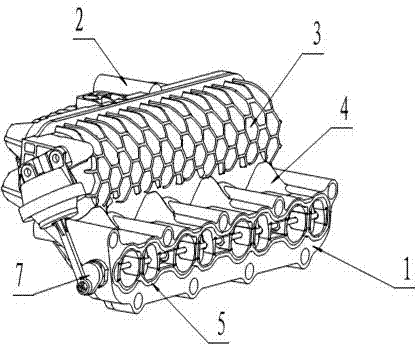
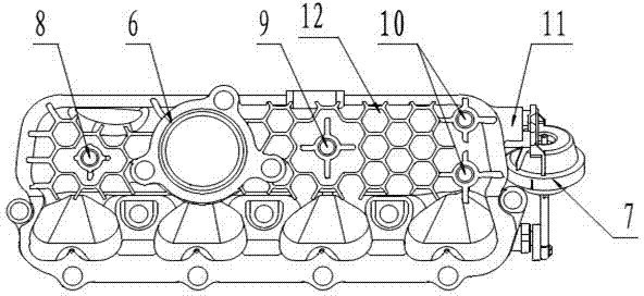
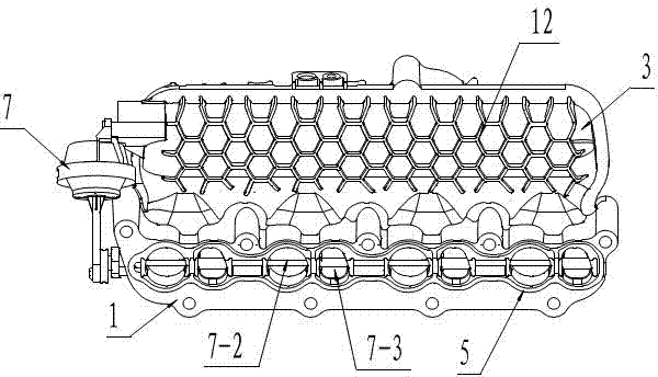
[0024] See Figure 1, figure 2 , the present invention includes an inlet flange 2, a pressure stabilizing chamber 3, an intake branch pipe 4, an outlet flange 1 and an intake swirl adjustment mechanism 7, and the inlet flange 2 is arranged on the same side as the intake branch pipe of the second cylinder of the engine. At the corresponding position, its front end is connected to the intake pipe behind the engine air filter, and its rear end is connected to the air inlet of the pressure stabilizing chamber. A group of intake branch pipes 4 are arranged on the opposite side walls, the rear ends of the intake branch pipes 4 communicate with the outlet flange 1, the axis of the intake branch pipe and the axis of the outlet flange form an included angle of 135°, and the outlet flange 1 is connected with the intake port of the engine cylinder head.

[0025] see Figure 1 to Figure 7 , the present invention is a cavity structure formed by vibration friction welding of upper and low...


PUM


Abstract

An engine intake manifold is used for matching the intake swirl to an engine under different operating conditions in order to enhance the comprehensive performance of the engine. The engine intake manifold comprises an inlet end flange, a pressure-stabilizing cavity, intake branches, an outlet end flange and an intake swirl regulation mechanism, the front end surface of the inlet end flange is connected with an intake connecting pipe behind an air filter of an engine, the rear end of the inlet end flange is connected with the air inlet of the pressure-stabilizing cavity, the pressure-stabilizing cavity is of a two-piece type butt joint structure, the group of intake branches are arranged on the sidewall opposite to the air inlet of the pressure-stabilizing cavity, the rear ends of the intake branches are connected with the outlet end flange, the axes of the intake branches make the included angle of 135 degrees with the axis of the outlet end flange, and the outlet end flange is connected with the intake passage of the cylinder head of the engine. The structure of the engine intake manifold is simple, and is compactly arranged, and the engine intake manifold can meet the requirement of the lightweight design of automobile engines, reasonably guide intake flow and improve the power performance, economic performance and emission indexes of engines.

Description

technical field [0001] The invention relates to an automobile engine intake manifold structure, which belongs to the technical field of combustion engines. Background technique [0002] In recent years, with the increase of automobile ownership and stricter emission regulations, energy saving and consumption reduction have become the main requirements of automobile engine design. In order to further improve the economic performance and emission index of the engine, more and more new technologies are adopted in the automobile engine. [0003] The intake manifold is the passage that sends air into each cylinder of the engine and plays a role in guiding the air flow. The structural characteristics of the intake manifold have an important impact on the performance parameters of the engine such as power, fuel consumption, torque and emissions. The disadvantage of the traditional intake manifold is that the airflow entering each cylinder of the engine is not uniform, so that the ...

Claims


Application Information

Patent Timeline
Patent Type & Authority Applications(China)
IPC IPC(8): F02M35/104F02D9/10
CPCY02T10/146Y02T10/12
Inventor 邵伟康张德胜刘占强周硕王建中
Owner GREAT WALL MOTOR CO LTD
Why Eureka
Try Eureka