Time-domain-pump-probe optical delay scanning device and method

A technology of optical delay and pump detection, which is applied in the directions of measuring devices, spectrometry/spectrophotometry/monochromator, optical radiation measurement, etc., can solve the problems such as the limitation of optical delay scanning range, and achieve the improvement of optical delay scanning. Scope, Effect of Reduced Requirements

Active Publication Date: 2013-03-06
HEFEI ZHICHANG PHOTOELECTRIC TECH
View PDF3 Cites 8 Cited by
  • Summary
  • Abstract
  • Description
  • Claims
  • Application Information

AI Technical Summary

Problems solved by technology

[0006] The technical problem to be solved by the present invention is to provide an optical delay scanning device and method for time-domain pumping detection. When the device is performing time-domain pumping detection, the optical delay scanning is performed on the pump beam and the detection beam at the same time, which solves the problem of The problem that the optical delay scanning range is limited by the moving range of the linear translation stage in the time-domain pump detection greatly reduces the requirement for the travel of the linear translation stage, or greatly increases the optical delay scanning range when the stroke of the linear translation stage remains unchanged

Method used


Image

  • Time-domain-pump-probe optical delay scanning device and method
  • Time-domain-pump-probe optical delay scanning device and method
  • Time-domain-pump-probe optical delay scanning device and method

Examples


Embodiment 1

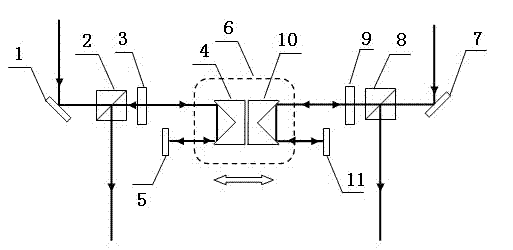
[0028] An optical delay scanning device for time-domain pumping detection, comprising a linear translation stage 6, a pumping light reflection mirror group 4 and a detection light reflection mirror group 10 arranged back to back on the linear translation platform 6, arranged on the pumping light reflection mirror group 10 in sequence The first pump light high reflection mirror 1, the pump light polarization splitting device 2 and the pump light 1 / 4 wave plate 3 at the front end of the light reflector group 4, the second pump light arranged at the rear end of the pump light reflector group 4 Light height reflector 5, the first detection light height reflector 7, detection light polarization splitting device 8 and detection light 1 / 4 wave plate 9 arranged in sequence at the front end of detection light reflection mirror group 10, arranged in detection light reflection mirror group The second detection light high reflector 11 at the 10 rear end; the light incident (exit) direction...

Embodiment 2

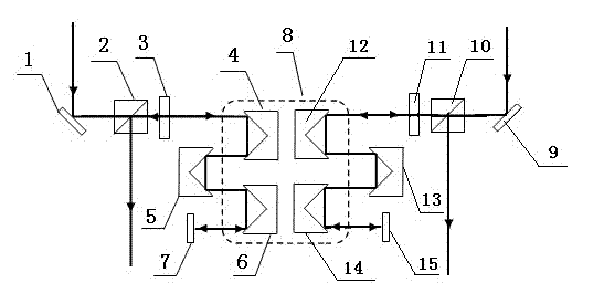
[0034] An optical delay scanning device for time-domain pumping detection, comprising a linear translation stage 8, three sequentially arranged pump light reflector groups 4, 5, 6, and three sequentially arranged probe light reflector groups 12, 13, 14, the first pump light high-reflection mirror 1, the pump light polarization splitting device 2 and the pump light 1 / 4 wave plate 3 arranged in sequence at the front end of the pump light reflector group 4 at the head end are arranged at the end The second pump light high reflector 7 at the rear end of the pump light reflector group 6 is sequentially arranged on the first detection light high reflector 9 at the front end of the head probe light reflector group 12, the probe light polarization splitter 10 and the detection The light 1 / 4 wave plate 11 is arranged on the second detection light high mirror 15 at the rear end of the end detection light reflection mirror group 14;

[0035] The head end pump light reflector group 4, the...


PUM


Abstract

The invention discloses a time-domain-pump-probe optical delay scanning device and a time-domain-pump-probe optical delay scanning method. The optical delay scanning device comprises a linear translation platform, and a pump light reflector set and a probe light reflector set which are arranged on the linear translation platform in a back-to-back way, wherein both arrangement directions of the pump light reflector set and the probe light reflector set guarantee that the incidence direction or the emergence direction of the light is consistent with the movement direction of the linear translation platform. When time-domain-pump-probe is performed, optical delay scanning is simultaneously performed on a pump light beam and a probe light beam, the problem of limitation of an optical delay scanning range in the time-domain-pump-probe to the movement range of the linear translation platform is solved, the requirement on travel of the linear translation platform is greatly reduced, or the optical delay scanning range is greatly expanded under the condition that the travel of the linear translation platform is not changed.

Description

[0001] technical field [0002] The invention relates to the field of time domain pump detection, in particular to an optical delay scanning device and method for time domain pump detection. Background technique [0003] In recent years, with the rapid development of ultrafast laser technology, time-resolved-pump-probe (Time-resolved-pump-probe) technology has attracted more and more attention. The time-domain pump-probe technology usually divides a beam of pulsed laser light into a beam of stronger pump light and a beam of weaker probe light. Among them, the pump light interacts with the sample to be tested, causing the change of the sample; the change of the sample is detected by the probe light. According to the test result, the information of the sample can be obtained. This technology has been widely used in the fields of terahertz time-domain spectral analysis and imaging detection, molecular and electron dynamics analysis and detection. [0004] In time-domain pump...

Claims


Application Information

Patent Timeline
Patent Type & Authority Applications(China)
IPC IPC(8): G01J3/06G01N21/17G01N21/01
Inventor 陈坚吴周令
Owner HEFEI ZHICHANG PHOTOELECTRIC TECH
Why Eureka
Try Eureka