
Method for discriminating influence of onshore pipeline oil leakage on water

A technology for oil leakage and identification methods, which is applied in pipeline systems, gas/liquid distribution and storage, special data processing applications, etc. question

Active Publication Date: 2013-03-06
PIPECHINA SOUTH CHINA CO
View PDF2 Cites 6 Cited by
  • Summary
  • Abstract
  • Description
  • Claims
  • Application Information

AI Technical Summary

Problems solved by technology

[0007] (1) QRA technology, as a quantitative risk assessment method for station equipment and facilities, cannot solve the identification and evaluation of the leakage path and leakage impact range of land long-distance pipelines, especially the impact evaluation on water bodies such as rivers and oceans;
[0008] (2) The QRA technology does not fully consider the terrain and terrain factors, but only considers the calculation of one-dimensional space, and the evaluation results are expressed in traditional charts, which cannot well display the spatial distribution of the evaluation results;
[0009] (3) QRA technology is a kind of refined risk assessment. Its research scale is small, the amount of data is large, and the identification process is complicated. It is not suitable for the identification and evaluation of multiple scenarios of large-scale and large-scale long-distance onshore pipelines.
[0014] (1) The DEM-based hydrological evaluation technology is aimed at the simulation analysis of the flow process of the surface water system, without considering the professional background of pipelines, and cannot be directly used for the identification and evaluation of oil leakage in land pipelines;
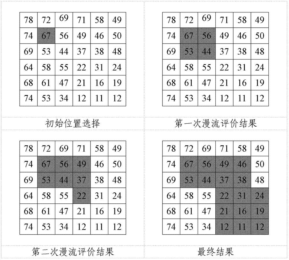
[0015] (2) Although the hydrological evaluation technology based on DEM can reproduce the flow of water flow, it has certain limitations in judging the scope of oil leakage; the main reason is that the hydrological evaluation only considers the location with the largest terrain drop around the study area, which is regarded as In the next direction of water flow, the results are often distributed linearly, which does not conform to the actual oil leakage situation;

Method used


Image

  • Method for discriminating influence of onshore pipeline oil leakage on water
  • Method for discriminating influence of onshore pipeline oil leakage on water
  • Method for discriminating influence of onshore pipeline oil leakage on water

Examples


Embodiment

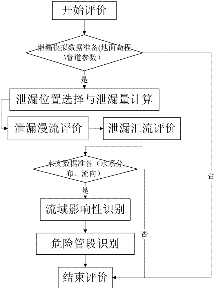
[0114] Embodiment. This example is an experimental method, and this embodiment has shown the discriminating process that the present invention is applied to pipeline, and its flow process is as follows figure 1 shown.

[0115] 1. Leak scene setting

[0116] Simulation scenario: large leak, the hole diameter of the leak point is 50mm, and the leak time is 12 hours;

[0117] Basic parameters of the pipeline: the pipeline delivery pressure is 6.4MPa, and the pipe diameter is φ529mm;

[0118] Figure 4 Shows the selected leak simulation points;

[0119] Use empirical calculation formulas to calculate the leakage at each leakage location, as shown in Table 7-1:

[0120] Table 7-1 Leakage at the leak location

[0121]

Leakage (m 3 )

Leakage (m 3 )

Leakage (m 3 )

1# position

4737

2# position

6148

3# position

6701

4# position

7200

5# position

6664

6# position

6900

7# positio...


PUM


Abstract

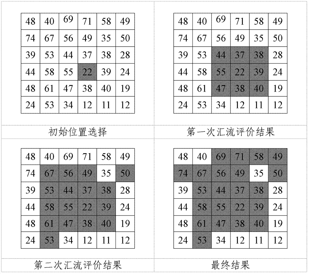
The invention provides a method for discriminating influence of onshore pipeline oil leakage on water, and relates to the technical field of measuring, sewage processing and piping systems excluded by the other methods. The method sequentially includes: 1), preparation for leakage analog data; 2), preparation for a leakage position and calculation of leakage rate; 3), evaluation of leakage sheetflood; 4), evaluation of leakage confluence; 5), preparation for hydrologic data; 6), discrimination of river basin influence; 7), discrimination of dangerous pipe sections; and 8), ending. By the aid of the method, a leakage path can be determined, a water source area possible to be affected and the dangerous pipe sections can be discriminated, an analysis result is displayed in a map manner, the method is visual in display means and is easy to understand.

Description

technical field [0001] The invention relates to a method for discriminating the impact of oil leakage from land pipelines on water bodies, and relates to the technical fields of measurement, sewage treatment and pipeline systems not included in other categories. Background technique [0002] Mainly compare the present quantitative risk assessment technique (QRA) and the hydrological assessment technique based on the digital elevation model with the present invention. [0003] 1. Quantitative risk assessment technology (QRA) [0004] Based on a large amount of data, QRA identifies various possible hazard sources. On this basis, by analyzing and comparing the historical failure accident data of similar equipment and facilities, the possibility of accident occurrence is analyzed, and the consequences of accident occurrence are simulated to finally form a risk assessment. result. As a purely quantitative evaluation method, QRA’s evaluation results are all numerical values. At ...

Claims


Application Information

Patent Timeline
IPC IPC(8): G06F19/00F17D5/02
Inventor 贾韶辉郭磊冯庆善周利剑李祎余海冲刘亮
Owner PIPECHINA SOUTH CHINA CO
Learn More