Dynamic latch comparator

A latching comparator and dynamic technology, applied in electrical components, electronic switches, pulse technology, etc., can solve the problems of static power consumption, circuit increase, etc., and achieve the effect of kickback noise reduction and low power consumption

Inactive Publication Date: 2013-03-06
ANYKA (GUANGZHOU) MICROELECTRONICS TECH CO LTD
View PDF3 Cites 19 Cited by
  • Summary
  • Abstract
  • Description
  • Claims
  • Application Information

AI Technical Summary

Problems solved by technology

Adding a source follower requires additional static power consumption of two branches
The introduction of two-phase non-ove

Method used


Image

  • Dynamic latch comparator
  • Dynamic latch comparator
  • Dynamic latch comparator

Examples


Embodiment 1

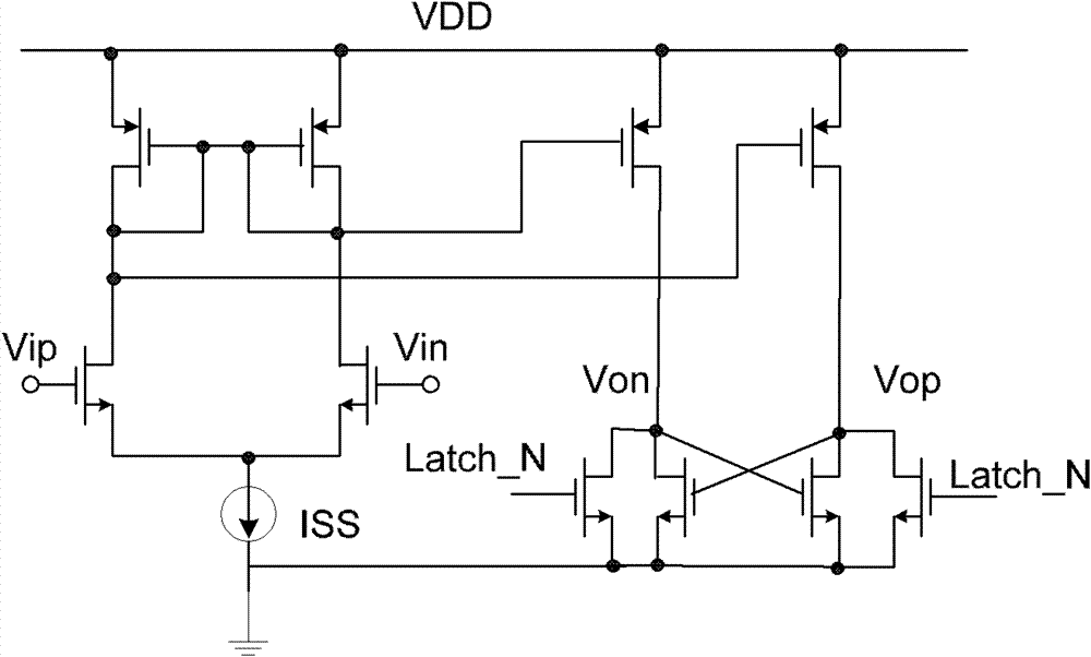
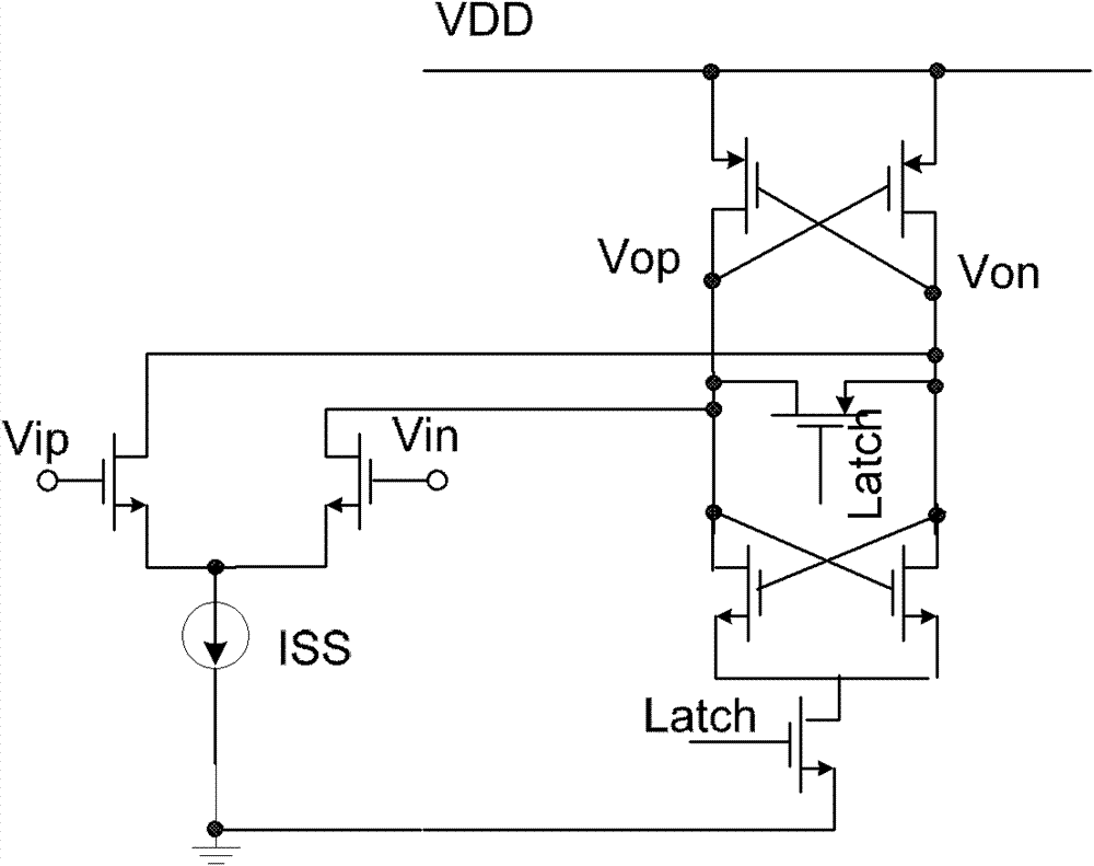
[0039] see image 3 , represents a preferred embodiment of the latch comparator of the present invention. Such as image 3 As shown, the input pair of the latch comparator is an NMOS transistor, which is compared to Figure 2c In the circuit shown, four NMOS transistors NM1, NM2, NM3 and NM4 are added, so that kickback noise can be better reduced on the basis of low power consumption. Combine below Figure 2c ,Comparative analysis image 3 The working principle and working process of the latched comparator circuit shown:

[0040] Such as Figure 2c As shown, there are no above-mentioned 4 NMOS transistors. In the reset period, the output terminals Vop and Von are both VDD, and the drain terminal of the input pair transistor is also VDD. When the latch enable signal latch changes from low potential to high potential, it enters the regeneration cycle, and the NMOS controlled by latch at the bottom of the circuit is turned on. At this time, the input pair has a current pul...

Embodiment 2

[0046] see Figure 4 , represents another preferred embodiment of the latch comparator of the present invention. Figure 4 In the circuit, both the input pair tube and the switch tube are PMOS, and correspondingly, the PMOS / NMOS tubes in other parts are changed accordingly. The working principle of the circuit is similar to that of the first embodiment, and will not be repeated here.

[0047] The latch comparator circuit of the above embodiment is very simple, while ensuring its low power consumption, it can make the kickback noise of the latch comparator smaller, and it has been applied to the development process of a product (IP 12bit sar adc) , simulation experiments show that it has better performance.


PUM


Abstract

The invention relates to the field of latch comparator circuit structures and discloses a dynamic latch comparator. The dynamic latch comparator comprises a first switch circuit and a second switch circuit which are controlled by a normal phase latch signal, and a third switch circuit and a fourth switch circuit which are controlled by a negative phase latch signal, wherein the first switch circuit is connected between the regeneration node of a first positive feedback anode and the output end of a first input pipe; the second switch circuit is connected between the regeneration node of a second positive feedback anode and the output end of a second input pipe; the third switch circuit is connected between the output end of the first input pipe and a ground/power supply; and the fourth switch circuit is connected between the output end of the second input pipe and the ground/power supply. According to the invention, four switch circuits are added on the basis of the existing dynamic latch to stabilize the electric potential at the output end of the input pipe at a resetting period and a regeneration period, so that the kickback noise can be effectively reduced on the basis of low power consumption.

Description

technical field [0001] The invention relates to a circuit structure of a latch comparator, in particular to a simple dynamic latch comparator with low power consumption and low kickback noise. Background technique [0002] Latch is to temporarily store the signal to maintain a certain potential state. A latch (Latch) is a memory unit circuit sensitive to pulse potentials, which can change its state under the action of a specific input pulse potential. Its main function is to cache, and the second is to complete the asynchronous problem between the high-speed controller and the slow peripherals. , followed by solving the driver problem, and finally solving the problem that the I / O port can both output and input. The latching comparator is the most commonly used circuit in high-speed comparators, which can realize the comparison of the magnitude of fast signals. [0003] Common latched comparators (reproducible equivalent structures such as figure 1 shown. In the reset per...

Claims


Application Information

Patent Timeline
IPC IPC(8): H03K5/22H03K17/16
Inventor 潘少辉胡胜发
Owner ANYKA (GUANGZHOU) MICROELECTRONICS TECH CO LTD
Why Eureka
Try Eureka