Low noise ECG cable and electrical assembly

A cable assembly, low-noise technology, applied in the field of low-noise ECG cables and electrical assemblies, can solve problems such as worsening triboelectric noise

Active Publication Date: 2013-03-06
TECHN SERVICES FOR ELECTRONICS
View PDF7 Cites 3 Cited by
  • Summary
  • Abstract
  • Description
  • Claims
  • Application Information

AI Technical Summary

Problems solved by technology

This can worsen the effect of triboelectric noise

Method used


Image

  • Low noise ECG cable and electrical assembly
  • Low noise ECG cable and electrical assembly
  • Low noise ECG cable and electrical assembly

Examples


Embodiment Construction

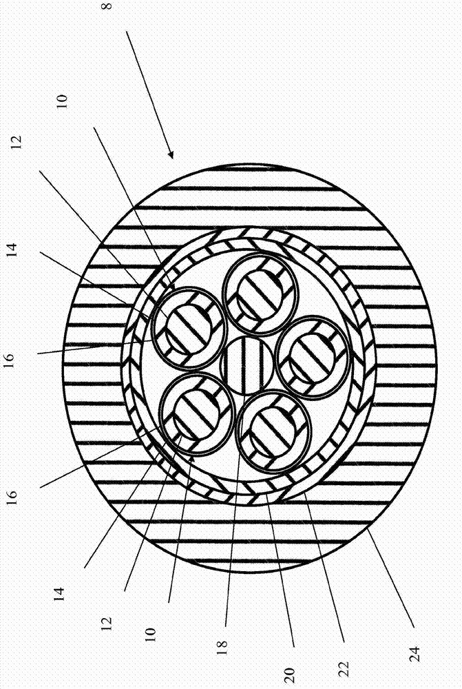
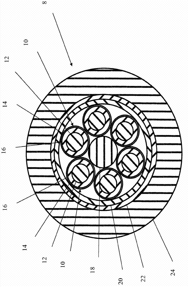
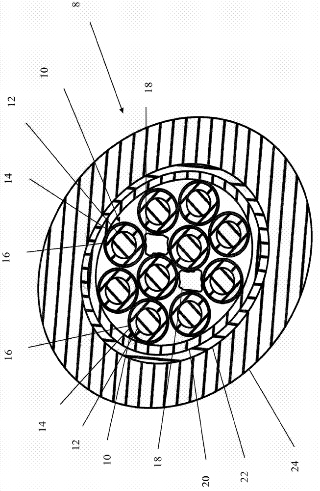
[0013] In a preferred embodiment, the invention takes the form of an ECG trunk cable 8 in which a set of leads 10 are encapsulated together around a central circular filler 18 . refer to figure 1 , the lead 10 includes a copper conductor 12 surrounded by a polypropylene insulator 14 . The polypropylene insulator is in turn sheathed by a low noise coating wall 16 . The leads 10 are tightly bound together by a semiconductive encapsulation 20 made of semiconductive PTFE tape. The semi-conductive enclosure is surrounded by a conductive shield 22 made of braided tinned copper. The entire cable is then surrounded by a polypropylene insulating sheath 24 . refer to figure 2 , the filler 18 can be made larger to accommodate more than five leads 10, or made smaller to accommodate fewer leads; common numbers of leads are three, five, six or ten. image 3 A ten-lead cable is shown, in which two fillers 18 are used, and which has a slightly elliptical cross-sectional shape. The fill...


PUM


Abstract

An electrocardiography (ECG) electrical cable, that includes a plurality of insulated conductors, a conductive shield surrounding the plurality of insulated conductors and an insulating jacket surrounding the plurality of insulated conductors and the conductive shield. Also, each of the plurality of insulated conductors includes a low noise coating and the insulated conductors are tightly bound together by a semi -conductive wall interposed between the insulated conductors and the shield, thereby reducing rubbing, which can produce triboelectric effects.

Description

Background technique [0001] Electrocardiography (ECG) is a means of detecting the electrical activity of the human heart through electrodes. These electrodes are attached to the skin and their signals are relayed to the ECG machine via leads tied into a trunk cable. The leads are made of a conductor (usually tinned copper) surrounded by an insulator (which may be polypropylene). The leads are then gathered together into a trunk, which is then provided with a shield (usually made of helically wound or braided tinned copper) and a surrounding insulating sheath (which may be polypropylene). In order to make the cable flexible, and to avoid any contact damage between the shield and the leads, the leads are usually loosely bound. [0002] The signals received by the electrodes are very weak, typically in the millivolt range, so minimizing noise is critical. The shield prevents external electromagnetic interference, but internal triboelectric noise remains a problem. The cables ...

Claims


Application Information

Patent Timeline
Patent Type & Authority Applications(China)
IPC IPC(8): H01B11/06H01B9/02A61B5/308
CPCH01B11/1066A61B5/04286H01B7/04A61B5/303H01B9/02H01B11/06
Inventor D·万德勒K·米克尔森
Owner TECHN SERVICES FOR ELECTRONICS
Why Eureka
Try Eureka