
LED light signal

A technology of optical signal and feedback signal, which is applied in the direction of signal device, visible signal device, railway signal and safety, etc. It can solve the problem of limited number of colors and achieve the effect of low manufacturing cost

Inactive Publication Date: 2013-03-06
SIEMENS AG
View PDF4 Cites 0 Cited by
  • Summary
  • Abstract
  • Description
  • Claims
  • Application Information

AI Technical Summary

Problems solved by technology

But always energizes LEDs of the same color so that the number of colors that can be displayed is also limited by the number of LEDs of different colors

Method used


Image

  • LED light signal
  • LED light signal
  • LED light signal

Examples


Embodiment Construction

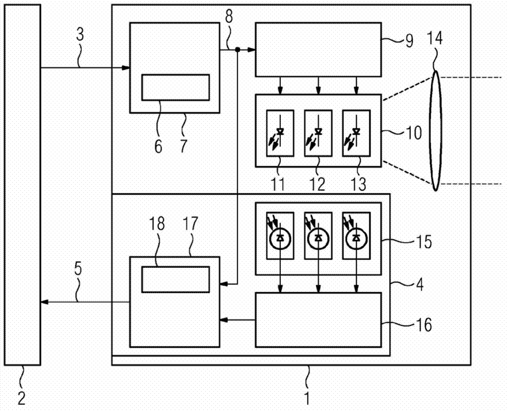
[0032] The LED railway light signal basically consists of a signal generator 1 which is controlled 3 by a console 2 and has components for light radiation and a monitoring device 4 which is connected to the console 2 via a feedback 5 .

[0033] The request for the signal generator 1 transmitted from the console 2 to the control device 7 equipped with the temperature sensor 6 contains information about the signal pattern of the requested signal generator 1 , in particular about the color and the light intensity. In the control device 7, the required information is associated with the output signal of the temperature sensor 6 for generating the target signal 8, which is converted by the LED driver 9 into three control signals for at least one RGB-LED 10, where RGB - LED 10 has individual LEDs 11 , 12 and 13 for red, yellow and blue.

[0034] The color of the light output by the optical system 14 is defined by the correlation of the three control signals for red, yellow and blue...


PUM


Abstract

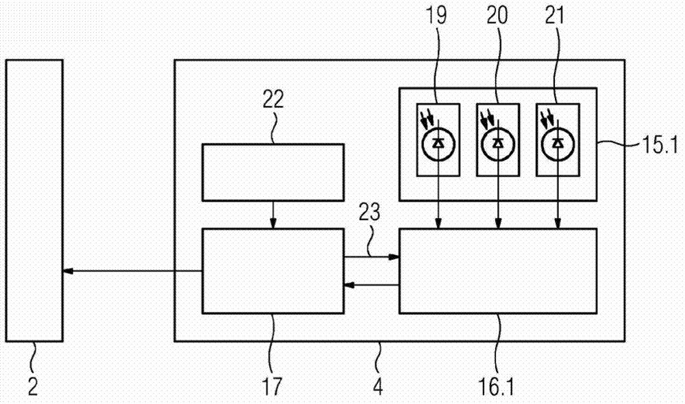
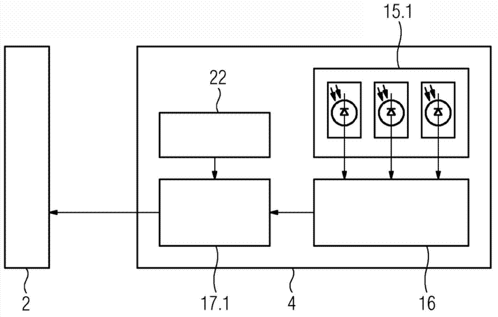
The invention relates to an LED light signal, in particular an LED railway light signal, comprising a signal generator (1) for generating varicoloured light spots, wherein the LEDs are embodied as multicolour LEDs, in particular RGB LEDs (10) - Red (11) / Yellow (12) / Blue (13) LEDs. In order to be able to utilize the possibilities for colour mixing and thus for realizing a large number of colour variants for safety-relevant signalling technology, the invention provides for the signal generator (1) to have at least one optical sensor (15, 15.1, 15.2) for monitoring the colour locus and the light intensity reliably in terms of signalling technology.

Description

technical field [0001] The invention relates to an LED light signal, in particular an LED railway light signal, with a signal generator for generating light spots of different colors, wherein the LEDs are configured as multicolor LEDs, in particular RGB-LEDs, i.e. red / yellow / Blue LEDs. Background technique [0002] The following explanations basically relate to light markings or light signals for signaling concepts in the case of rail vehicles, without the content of the claimed invention being restricted to this application. [0003] Light signals or light signs based on LEDs, ie light-emitting diodes, are increasingly being used instead of incandescent lamps in many fields, in particular in railway signaling technology. LEDs are relatively inexpensive, have a long life and high light intensity. The trend here is in the direction of HLEDs, ie high-flux LEDs, whose luminous intensity is so high that an individual HLED per light spot is already sufficient to emit light to ...

Claims


Application Information

Patent Timeline
Patent Type & Authority Applications(China)
IPC IPC(8): H05B33/08H05B44/00
CPCB61L5/1827B61L5/1881G08B5/36B61L2207/02H05B45/58H05B45/22H05B45/327
Inventor E.伯格R.埃克尔N.波普罗
Owner SIEMENS AG
Learn More