Multifunctional glass cleaning robot and control method

A cleaning robot, multi-functional technology, applied in the field of robots, can solve the problems of large influence of working space and glass thickness, low safety factor, excessive mechanical load, etc., to achieve good scrubbing effect, enhance safety, and save resources.

Inactive Publication Date: 2013-03-13
HUNAN UNIV OF SCI & TECH
View PDF9 Cites 37 Cited by
  • Summary
  • Abstract
  • Description
  • Claims
  • Application Information

AI Technical Summary

Problems solved by technology

For example, most of the products developed in the initial research have shortcomings such as large size, complex structure, cumbersome operation, poor stability, and low safety factor.
For example, the patent application number is: CN201110436290.0, the publication number is: CN102556196A, and the publication date is: 2012-07-11. "A magnetic adsorption type wall-climbing robot" uses double-sided magnetic force adsorption, and is affected by the working space and the glass. The influence of the thickness is large, and the safety factor is relatively reduced; the patent application number is: CN201120241153.7, the publication number is: CN202156471U, and the publication date is: 2012-03-07 The "suction cup type pneumatic wall climbing robot" is cumbersome to operate, poor coordination and stability
The patent number is: 200810064947.3, the authorized announcement number is CN 101317744 B, and the authorized announcement date is June 09, 2010. "The wall cleaning robot based on the principle of positive and negative pressure", its sewage collection device brings mechanical load overload Large size, low safety, and the existence of dead angle problems make the cleaning efficiency not high

Method used


Image

  • Multifunctional glass cleaning robot and control method
  • Multifunctional glass cleaning robot and control method
  • Multifunctional glass cleaning robot and control method

Examples


Embodiment Construction

[0033] The technical scheme of the present invention will be further described below in conjunction with the accompanying drawings and through specific embodiments:

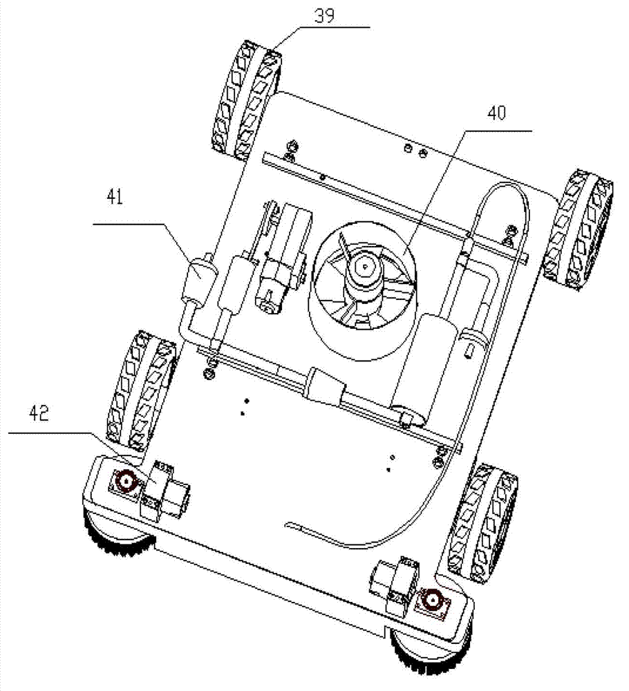
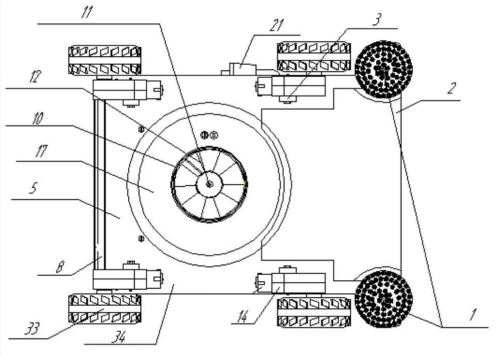
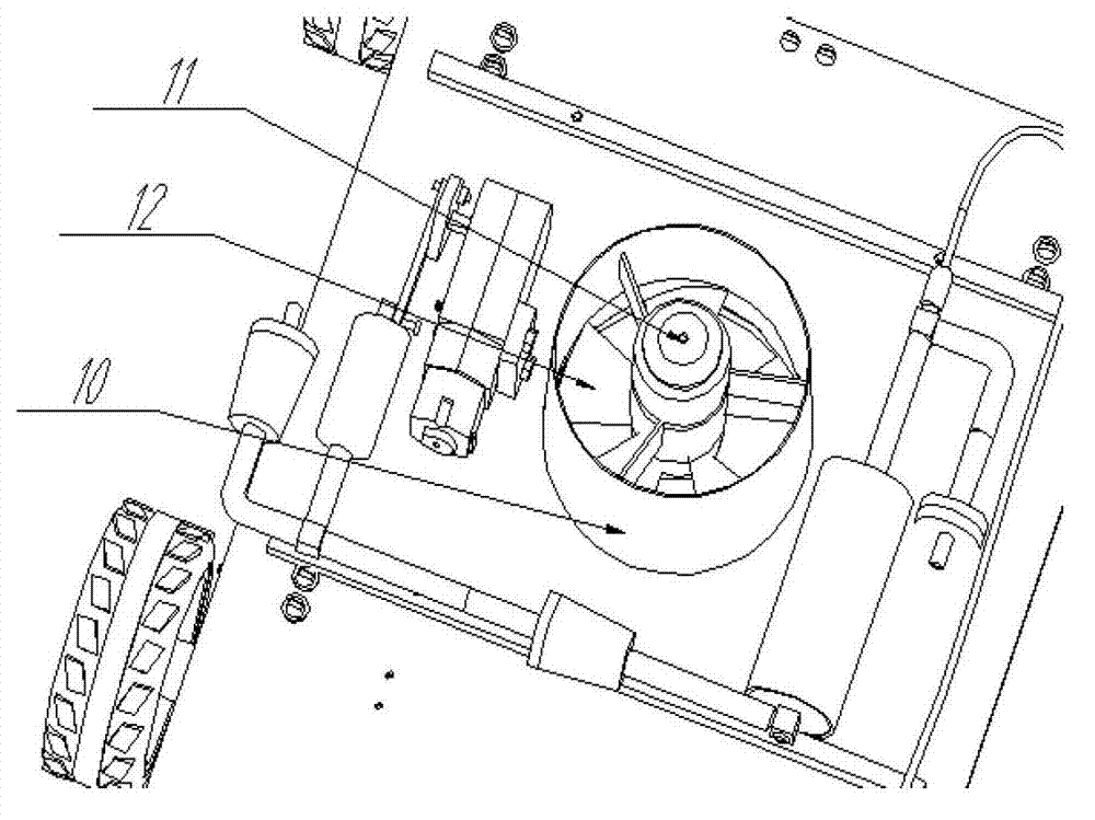
[0034] Please refer to Figure 1 to Figure 8 , providing a multifunctional glass cleaning robot for the present invention, including a box body 5, an adsorption system 40, a walking steering system 39, a water supply system 41, a cleaning system 42 and an automatic control system (not shown), the adsorption system 40 and the water supply system 41 are installed in the box body 5 , and the walking steering system 39 and the cleaning system 42 are installed in the lower part of the box body 5 .

[0035] The automatic control system includes a central controller, an infrared remote sensor and an alarm device, the central controller is used to control the walking steering system 39, and the central controller is powered by a rechargeable battery, and the alarm device is preset with Alarm threshold, alarm when the po...


PUM


Abstract

The invention discloses a multifunctional glass cleaning robot and a control method. The multifunctional glass cleaning robot comprises a box body, an adsorption system, a walking steering system, a water supply system, cleaning systems and an automatic control system, wherein the adsorption system and the water supply system are mounted in the box body; the walking steering system and the cleaning systems are mounted at the lower part of the box body; the adsorption system comprises a three-phase motor, a pneumatic cavity, a duct and a fan blade; the walking steering system comprises four sets of wheeled structures; each set of the wheeled structures comprises a DC motor, a reducer, a wheel and a fixing plate; the water supply system comprises a crank shaft cam mechanism, and further comprises a gas guiding pipe, a water tank and a water supply guiding pipe which are connected in sequence; the cleaning systems comprise cleaning motors, bevel gears, glass brushes, glass scrapers and glass cloth; and the automatic control system comprises a central controller, an infrared remote sensor and an alarming device. The multifunctional glass cleaning robot has the advantages that the structure is simple; the carrying is convenient; the cost is low; no dead angle exists during cleaning; glass cleaning requirements of families, office spaces and the like are met; and the market application prospect is wide.

Description

technical field [0001] The invention relates to the field of robots, in particular to a multifunctional glass cleaning robot and a control method. Background technique [0002] Cleaning robots are the main application fields of existing service robots at home and abroad. In today's high-rise buildings, the demand for glass cleaning has promoted the rapid development of this type of robot technology and the upgrading of products. The safe and efficient cleaning of indoor glass is also increasingly concerned by people. In this way, the multifunctional glass cleaning robot comes into being. [0003] Traditional glass cleaning robots have basically realized automatic and semi-automatic control methods, but there are still many defects in various aspects. For example, most of the products developed at the initial stage have disadvantages such as large size, complex structure, cumbersome operation, poor stability, and low safety factor. For example, the patent application numbe...

Claims


Application Information

Patent Timeline
Patent Type & Authority Applications(China)
IPC IPC(8): A47L1/02
Inventor 康辉民解少轩李芹刘花张登周浩
Owner HUNAN UNIV OF SCI & TECH
Why Eureka
Try Eureka