Sewage filtering device
A filtration device and sewage technology, applied in the direction of filtration separation, filtration loop, separation method, etc., can solve the problems of reducing sewage treatment efficiency, hindering sewage from passing through the filter element, etc., achieving good effect, preventing deformation or rupture, and improving service life.
- Summary
- Abstract
- Description
- Claims
- Application Information
AI Technical Summary
Problems solved by technology
Method used
Image
Examples
Embodiment 1
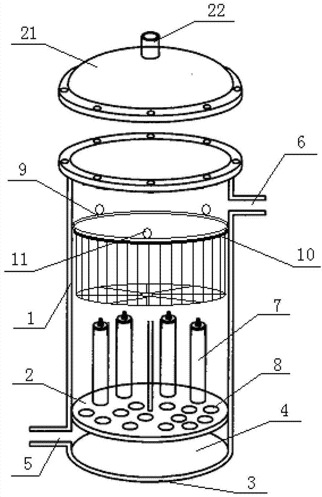
[0027] like figure 1 As shown, a sewage filtering device includes a cylinder body 1 and a filter cover 9 . A support plate 2 is provided at the lower end of the cylinder body 1 . A water production chamber 4 is formed between the cylinder base 3 and the support plate 2 , and the water production chamber 4 is provided with a water outlet 5 . A water inlet 6 is arranged on the cylinder body 1 , and an annular support 10 is provided on the inner wall of the cylinder body 1 below the water inlet 6 , and the filter cover 9 is placed on the annular support 10 . The support plate 2 is provided with a plurality of hollow filter elements 7 , and the support plate 2 is provided with a drain hole 8 connecting the hollow of the filter elements 7 with the water production chamber 4 .
[0028] The filter cover 9 includes a cylindrical support and a filter membrane, and the filter membrane is fixed on the inner wall of the cylindrical support. The filter membrane is made of polypropylene ...
Embodiment 2
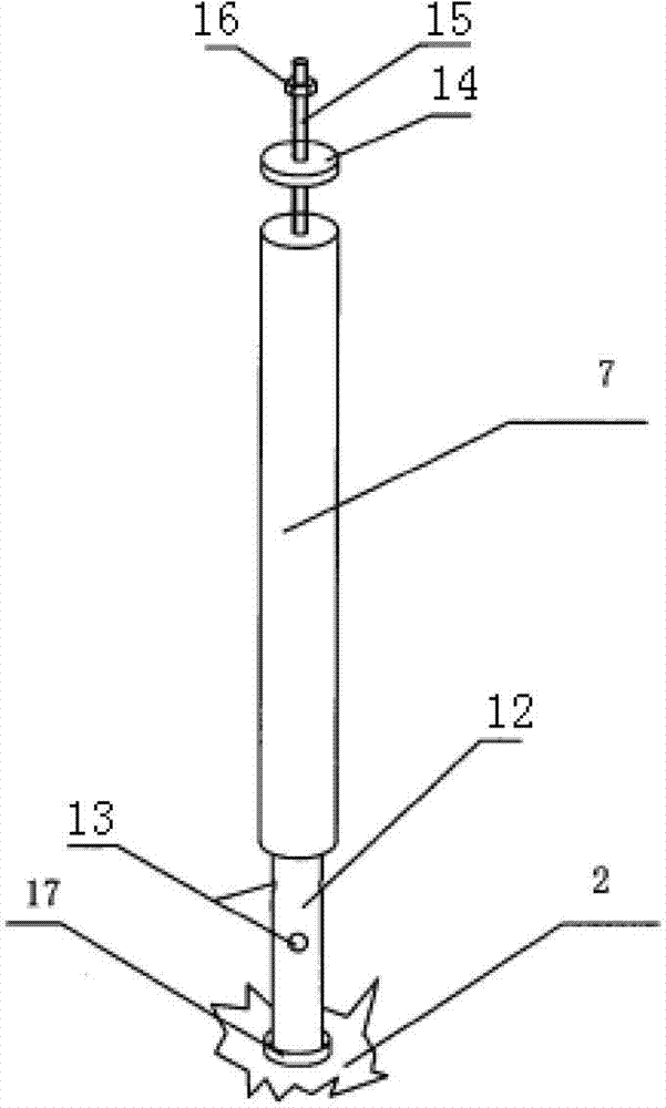
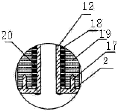
[0031] like figure 2 , image 3 As shown, the filter element 7 is provided with a hollow filter element support tube 12 , and a plurality of filter element water permeable holes 13 are provided on the side wall of the filter element support tube 12 . A filter element cap 14 is fixedly arranged on the filter element 7 . The filter element 7 includes a skeleton 18 and a polypropylene layer 19 , and the polypropylene layer 19 is located outside the skeleton 18 . A plurality of water filtering holes 20 are distributed on the skeleton 18 , and the outer surface of the filter element support tube 12 is closely connected to the inner surface of the skeleton 18 . A cap (not shown) is fixed on the filter support tube 12, a screw 15 is fixed on the cap, the filter cap 14 is set on the screw 15, and the filter cap 14 is fixed on the filter element 7 with a nut 16. The setting of the tube cover can prevent untreated water from entering from the upper end of the filter element support ...
Embodiment 3
[0036] see figure 2 and image 3 , This embodiment is the same as Embodiment 2 except for the structure of the filter core. The outer surface of the filter element in this embodiment is wrapped with a hollow filter element support tube, and a plurality of filter element water permeable holes are arranged on the side wall of the filter element support tube. A filter element cap is fixedly arranged on the filter element, and the filter element cap is movably connected with the filter element support pipe. The filter element includes a skeleton and a polypropylene layer, the polypropylene layer is located outside the skeleton, and a plurality of water filtering holes are distributed on the skeleton, and the outer surface of the polypropylene layer is close to the inner surface of the filter element support tube.
PUM
 Abstract
Description
Claims
Application Information
 - R&D
- Intellectual Property
- Life Sciences
- Materials
- Tech Scout
- Unparalleled Data Quality
- Higher Quality Content
- 60% Fewer Hallucinations
Browse by: Latest US Patents, China's latest patents, Technical Efficacy Thesaurus, Application Domain, Technology Topic, Popular Technical Reports.
© 2025 PatSnap. All rights reserved.Legal|Privacy policy|Modern Slavery Act Transparency Statement|Sitemap|About US| Contact US: help@patsnap.com


