
Telescopic machine head pressing column

A telescopic and pressure column technology, which is applied in the direction of conveyor objects, earth drilling, underground transportation, etc., can solve the problems of unfavorable safety production, collapse of pressure columns, etc., and achieve the effects of saving wood, easy operation and long service life

Inactive Publication Date: 2013-03-13
HENAN YONGHUA ENERGY
View PDF1 Cites 6 Cited by
  • Summary
  • Abstract
  • Description
  • Claims
  • Application Information

AI Technical Summary

Problems solved by technology

In actual use, it is found that the patent cannot be adjusted after it is well supported. Due to the vibration generated when the scraper conveyor is working, the pressure column must be loosened. After a long time of work, the pressure column is prone to collapse, which is not conducive to safe production.

Method used


Image

  • Telescopic machine head pressing column
  • Telescopic machine head pressing column

Examples


Embodiment Construction

[0016] The present invention is further described below in conjunction with embodiment; The following embodiment is not for the limitation of the present invention, only as the mode of supporting the realization of the present invention, any equivalent structural replacement within the technical framework disclosed in the present invention, all is the present invention. the scope of protection of the invention;

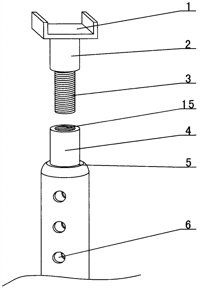
[0017] combined with figure 1 Or the telescopic head pressure column described in 2, including "U" shaped bracket 1, screw rod 3, threaded pipe 4, main support rod 7, height adjustment pipe 11, base plate 14, the upper end of screw rod 3 is connected to the steel pipe 2 At the lower end, the middle part of the bottom surface of the "U"-shaped bracket 1 is connected to the upper end of the steel pipe 2; the upper end of the main support rod 7 is provided with a threaded pipe 4, and the lower end of the threaded pipe 4 is necked and welded with the upper end of the main...


PUM


Abstract

The invention provides a telescopic machine head pressing column, relating to machine head pressing columns. According to the telescopic machine head pressing column, a big insertion column (13) on a bottom plate (14) is inserted in a pipe hole (8) in the lower part of a height adjusting pipe (11), the lower end of a main support rod (7) is inserted in a pipe hole (8) in the upper part of the height adjusting pipe (11), and the height locating of the main support rod (7) and the height adjusting pipe (11) is achieved realized in a manner that bolts penetrate into a through hole B (10) of the height adjusting pipe (11) and a through hole A (6) of the main support rod (7); and the fine adjustment of the height of the pressing column is achieved realized in a manner that a screw rod (3) at the lower part of a U-shaped bracket (1) is connected with a screw hole (15) of a screwed pipe (4). According to the telescopic machine head pressing column, the fine adjustment of height is realized by the screw rod at the lower part of the U-shaped bracket and the screwed pipe at the upper end of the main support rod, and the greater height adjustment is quickly realized in a manner that the bolts are applied to the through hole A in the main support rod and the through hole B in the height adjusting pipe, so that the technical long-cherished need that a machine head is high in stable coefficient and difficultly gets loose is realized.

Description

【Technical field】 [0001] The invention relates to a head pressure column, in particular to a telescopic scraper conveyor head pressure column. 【Background technique】 [0002] It is known that when the scraper conveyor is in use, pressure columns must be installed at the head and tail. Most of the existing pressure columns use high-quality round logs with a diameter of not less than ∮180mm. The head pressure column is installed on the bottom beam of the machine head on both sides of the machine head, and the tail pressure column is installed on the pressure column seat on both sides of the machine tail. One pressure column is installed on each side, two in total. The beam is installed at the reduction box at the front end of the machine head frame, and is fastened to the machine head frame with 4 M20 bolts. The head and tail pressure columns must be vertically installed and firm and reliable. When the scraper conveyor is running, the machine head , The tail of the machine sh...

Claims


Application Information

Patent Timeline
IPC IPC(8): B65G41/00E21F13/00
Inventor 郑明宗秦恒昌冉永兵
Owner HENAN YONGHUA ENERGY
Learn More