Electrolytic copper foil generator
A technology of electrolytic copper foil and raw foil machine, applied in the direction of electrolysis, electroforming, etc., can solve the problems of variable output speed of winding motor, instability, and difficulty in adapting to large winding radius, etc., to achieve flexible production time and structure Simple, effective in inhibiting oxidation blackening
- Summary
- Abstract
- Description
- Claims
- Application Information
AI Technical Summary
Problems solved by technology
Method used
Image

Examples
Embodiment 1
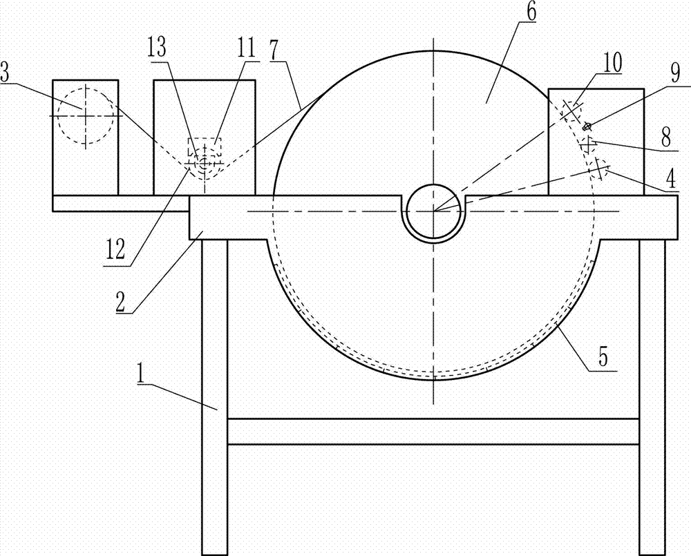
[0044] An electrolytic copper foil raw foil machine, such as image 3 As shown, it includes a frame 1, an anode tank 2, an anode plate 5, a cathode roll 6, a take-up roll 3, a squeezing roll 4, a brush roll 8, a water sprayer 9, a squeezing roll 10, and a tension roll. 12. The bearing seat 13 and the tension sensor 11, the outer layers of the squeezing roller 4 and the squeezing roller 10 are made of rubber material, and the squeezing roller 4 and the squeezing roller 10 are installed on the bearing and the bearing seat. On the side plates on both sides of the frame 1, the squeezing roller 4 is installed on the upper right of the cathode roller 6, and is in contact with the electrolytic copper foil 7 deposited on the cylindrical surface of the cathode roller 6, and the brush roller 8 is installed On the upper left of the squeezing roll 6, and in contact with the electrolytic copper foil 7 deposited on the cylindrical surface of the cathode roll 6, the squeezing roll 10 is inst...
Embodiment 2
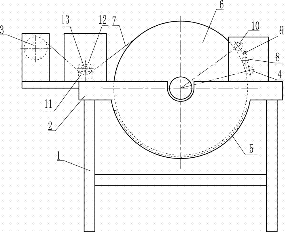
[0048] An electrolytic copper foil raw foil machine, such as figure 2 As shown, it includes a frame 1, an anode tank 2, an anode plate 5, a cathode roll 6, a take-up roll 3, a squeezing roll 4, a brush roll 8, a water sprayer 9, a squeezing roll 10, and a tension roll. 12. The bearing seat 13 and the tension sensor 11, the outer layers of the squeezing roller 4 and the squeezing roller 10 are made of rubber material, and the squeezing roller 4 and the squeezing roller 10 are installed on the bearing and the bearing seat. On the side plates on both sides of the frame 1, the squeezing roller 4 is installed on the upper right of the cathode roller 6, and is in contact with the electrolytic copper foil 7 deposited on the cylindrical surface of the cathode roller 6, and the brush roller 8 is installed On the upper left of the squeezing roll 6, and in contact with the electrolytic copper foil 7 deposited on the cylindrical surface of the cathode roll 6, the squeezing roll 10 is ins...
Embodiment 3
[0052] An electrolytic copper foil raw foil machine, including a frame 1, an anode tank 2, an anode plate 5, a cathode roll 6, a winding roll 3, a squeezing roll 4, a brush roll 8, a water sprayer 9, a squeezing roll The water roller 10, the tension roller 12, the bearing seat 13 and the tension sensor 11, the outer layers of the squeezing roller 4 and the squeezing roller 10 are made of rubber materials, and the squeezing roller 4 and the squeezing roller 10 pass through Bearings and bearing seats are installed on the side plates on both sides of the frame 1, the squeezing roll 4 is installed on the upper right of the cathode roll 6, and is in contact with the electrolytic copper foil 7 deposited on the cylindrical surface of the cathode roll 6, so The brush roller 8 is installed on the upper left of the squeezing roller 6, and is in contact with the electrolytic copper foil 7 deposited on the cylindrical surface of the cathode roller 6, and the squeezing roller 10 is installe...
PUM
 Abstract
Description
Claims
Application Information
 - R&D Engineer
- R&D Manager
- IP Professional
- Industry Leading Data Capabilities
- Powerful AI technology
- Patent DNA Extraction
Browse by: Latest US Patents, China's latest patents, Technical Efficacy Thesaurus, Application Domain, Technology Topic.
© 2024 PatSnap. All rights reserved.Legal|Privacy policy|Modern Slavery Act Transparency Statement|Sitemap