Control system of transmission

A technology for control devices and transmissions, applied in transmissions, vehicle gearboxes, gear transmissions, etc., can solve the problems of increased resistance, large load, and inconsistency in the rotation of synchronizing devices, and can prevent the increase in the number or weight of components. Effect

Active Publication Date: 2013-03-13
HONDA MOTOR CO LTD
View PDF7 Cites 3 Cited by
  • Summary
  • Abstract
  • Description
  • Claims
  • Application Information

AI Technical Summary

Problems solved by technology

[0006] However, in the above-mentioned conventional technology, there is a problem that since it is necessary to provide a special rotation restricting unit so that the synchronizing device can operate smoothly, the number of components or the weight increases the part of the rotation restricting unit.
In addition, in the above-mentioned conventional technology, there is also the following problem: Even in the state where the rotation of the first and second auxiliary input shafts is restricted by the rotation restricting means, the lubricating oil adhering to the friction plates of the first and second clutches Viscosity, the resistance to the rotation of the synchronization device increases, so it is not easy to make the phase of the sleeve and the gear of the synchronization device consistent, and a large load is still required in the work of the synchronization device

Method used


Image

  • Control system of transmission
  • Control system of transmission
  • Control system of transmission

Examples


Embodiment Construction

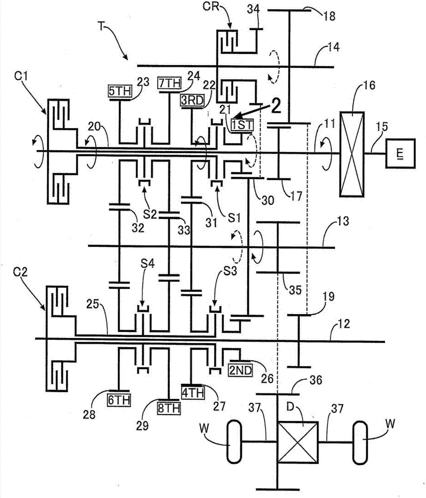
[0042] Below, based on Figure 1 to Figure 7 A first embodiment of the present invention will be described.

[0043] Such as figure 1 As shown, the twin-clutch transmission T having 8 forward speeds and 1 reverse speed includes a first input shaft 11 , a second input shaft 12 , an output shaft 13 , and an idler shaft 14 arranged in parallel to each other. A crankshaft 15 of the engine E is connected to a first input shaft 11 via a torque converter 16 that functions as a starter. The driving gear 17 fixedly arranged on the first input shaft 11 meshes with the idler gear 18 fixedly arranged on the idler shaft 14, and the idler gear 18 meshes with the driven gear 19 fixedly arranged on the second input shaft 12, so the second The input shaft 12 always rotates in the same direction with respect to the first input shaft 11 at a predetermined ratio, and the idler shaft 14 always rotates in the opposite direction with respect to the first input shaft 11 at a predetermined ratio.

...


PUM


Abstract

According to aspects of the disclosure, provided is a transmission control system to enable smooth engagement of meshing engagement means When establishing a forward gear position by engaging the meshing engagement means and a forward clutch while a vehicle is stationary. For example, when a synchro device is operated so as to establish a predetermined forward gear position, it becomes difficult to smoothly couple a first speed drive gear to the input shaft by the synchro device. However, temporarily engaging a reverse clutch during the process of operation of the synchro device allows a reverse torque to act on the first speed drive gear to apply torsion to a power transmission path between the first speed drive gear and a driven wheel. Furthermore, a repulsive force is applied and generates backlash between the synchro device and the first speed drive gear, thus enabling smooth operation of the synchro device.

Description

technical field [0001] The present invention relates to a control device for a transmission that establishes a predetermined forward shift speed through a frictional engagement element such as a wet multi-disc clutch and a meshing engagement unit such as a synchronizer. Background technique [0002] According to the following patent document 1, the following technology is known: in the dual clutch transmission equipped with a synchronizer, the first and second clutches provided between the main input shaft and the first and second auxiliary input shafts are provided The rotation limiting unit activates the synchronizer when the vehicle is stopped, and when the first gear or the reverse gear is pre-shifted, the first and second auxiliary input shafts are restricted by the rotation limiting unit due to the wet multi-disc clutch. The slip torque of the first and second clutches rotates, so the relative rotation between the synchronizer and the gears can be reduced and pre-shift...

Claims


Application Information

Patent Timeline
Patent Type & Authority Applications(China)
IPC IPC(8): F16H59/00F16H59/72F16H3/093F16H3/12
CPCF16H61/0437F16D23/06F16H2200/0078F16H2200/006F16H3/006F16H2061/047Y10T74/19233Y10T74/19251Y10T74/19284
Inventor 大森生雄
Owner HONDA MOTOR CO LTD
Why Eureka
Try Eureka