
Air guide curtain of air conditioner

An air curtain and air conditioner technology, which is applied in space heating and ventilation, heating and ventilation control systems, heating and ventilation safety systems, etc., can solve the problems of limited air guiding space, unreachable working conditions, and occurrence of colds in children. To achieve the effect of reducing air conditioning disease, slowing down the flow time, and simple operation

Inactive Publication Date: 2013-03-13
谢逢华
View PDF5 Cites 16 Cited by
  • Summary
  • Abstract
  • Description
  • Claims
  • Application Information

AI Technical Summary

Problems solved by technology

[0002] When the household wall-mounted air conditioner is running in the cooling and heating modes, the angle of the air guide plate at the air outlet is used to adjust the angle to change the direction of the air outlet. When cooling, the outlet air blows upwards, and the entire room is cooled due to the sinking of cold air; When heating, the hot air rises, and the air should be blown downward. At present, many air conditioner air deflectors are also designed according to this principle. However, since there is only one air deflector at the air outlet of the air conditioner on-hook, the air guide space is limited and cannot reach Ideal working condition, when heating, part of it is blown downward, most of it is still blown to the front, people stand and blow out warm air within 1 meter, when the distance exceeds this distance, the warm air blown out will feel like cold air, which is easy Cause headaches for the weak and / or children to catch a cold, and the existing air conditioners can't meet the corresponding requirements of people when the air is heated.

Method used


Image

  • Air guide curtain of air conditioner
  • Air guide curtain of air conditioner
  • Air guide curtain of air conditioner

Examples


Embodiment Construction

[0013] Below in conjunction with accompanying drawing, technical solution of the present invention is described further:

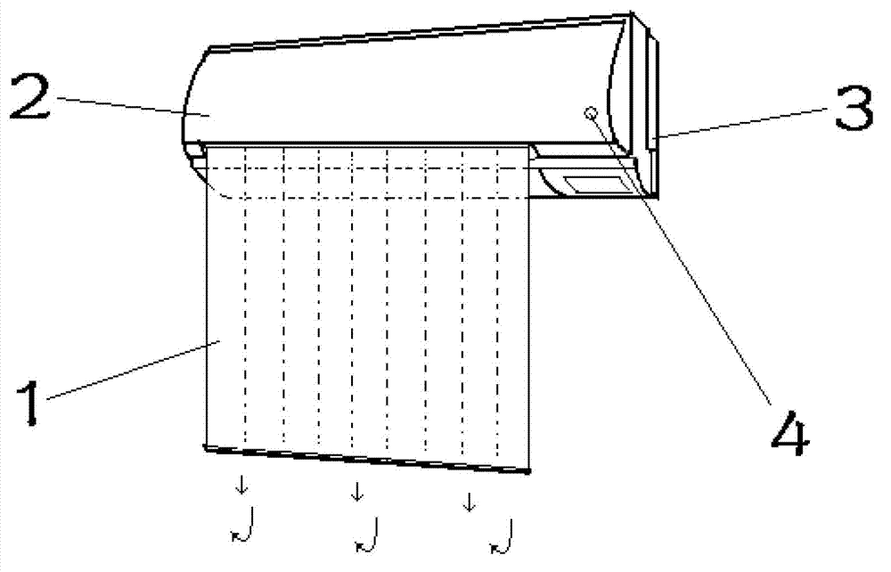
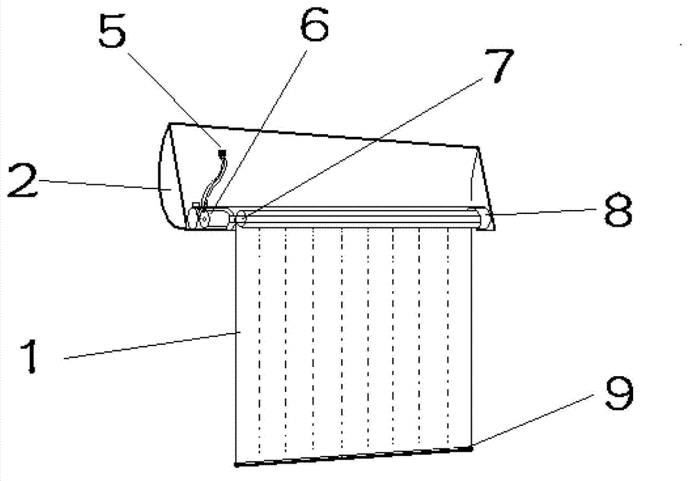
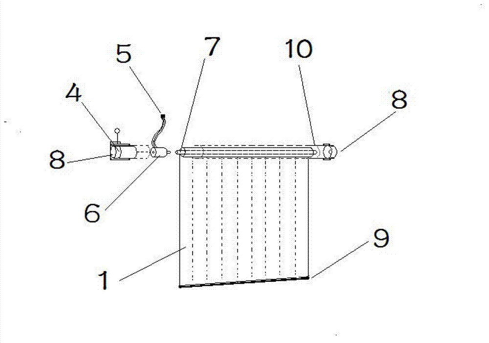
[0014] exist figure 1 figure 2 Among them, the air-conditioning air guide curtain of the present invention is directly installed in the air-conditioning indoor unit cover 2, and various specifications of air-conditioning indoor units or outside panels can also be installed independently. The machine cover 2, the controller 4, the power plug 5, the synchronous motor 6, the roller shutter shaft 7, the roller shutter fixing seat 8, the vertical curtain rod 9 and the roller shutter box 10. The roller shutter shaft 7 is connected, and the other side is connected with the vertical curtain rod 9. The roller shutter shaft 7 is connected to the synchronous motor 6 and placed in the left or side roller blind fixing seat 8, and the other side is placed in the right or left roller blind fixing seat 8. Among the connected bearings, the roller shutter box 10 is inst...


PUM


Abstract

The invention discloses an air guide curtain of an air conditioner. The air guide curtain is characterized in that one side of air curtain cloth of the air guide curtain is connected with a rolling blind shaft, and the other side of the air curtain cloth is connected with a curtain falling rod; one side of the rolling blind shaft is connected with a synchronous motor and is arranged in a rolling blind permanent seat on a left side, and the other side of the rolling blind shaft is arranged in a bearing connected in a rolling blind permanent seat on a right side and is arranged inside or outside an indoor unit surface cover through a rolling blind box; a left rolling blind permanent seat and a right rolling blind permanent seat are arranged; and a motor arranged in a controller is used for controlling a singlechip switch and a limiting switch, and is packaged in the left rolling blind permanent seat together with a receiving head. The air guide curtain of the air conditioner is simple in structure, and is easy to mount; functions of automatically starting up for falling the curtain during heating of the air conditioner and shutting down for rolling the curtain are designed, so that the conventional air supply mode of the air conditioner is changed; and an air deflector is prolonged through the air curtain cloth, so that hot air is guided to be lower side, cold air feel in a certain distance under the condition that central heating is started up in winter is avoided, the indoor temperature distribution is more uniform, and air-conditioning diseases are reduced.

Description

technical field [0001] The invention relates to an air conditioner air guide plate, in particular to a wall-mounted air conditioner air guide curtain. Background technique [0002] When the household wall-mounted air conditioner is running in the cooling and heating modes, the angle of the air guide plate at the air outlet is used to adjust the angle to change the direction of the air outlet. When cooling, the outlet air blows upwards, and the entire room is cooled due to the sinking of cold air; When heating, the hot air rises, and the air should be blown downward. At present, many air conditioner air deflectors are also designed according to this principle. However, since there is only one air deflector at the air outlet of the air conditioner on-hook, the air guide space is limited and cannot reach Ideal working condition, when heating, part of it is blown downward, most of it is still blown to the front, people stand and blow out warm air within 1 meter, when the distanc...

Claims


Application Information

Patent Timeline
Patent Type & Authority Applications(China)
IPC IPC(8): F24F13/10F24F11/02
Inventor 谢逢华
Owner 谢逢华
Learn More