
Grease injection head facilitating conductive grease filling of strain clamp

A technology of tension-resistant clamp and conductive grease, which is applied to the device and coating of the surface coating liquid, which can solve the problems of increasing the work intensity of the operator, the inaccurate positioning of the grease injection head, and the waste of conductive grease. Achieve the effect of avoiding mutual sliding, meeting operation requirements and improving injection efficiency

Pending Publication Date: 2019-11-19
ZHEJIANG HUADIAN EQUIP TESTING INST
View PDF0 Cites 0 Cited by
  • Summary
  • Abstract
  • Description
  • Claims
  • Application Information

AI Technical Summary

Problems solved by technology

[0003] In order to effectively prevent rainwater from intruding into the non-pressing area of ​​the tension clamp to cause freezing and swelling, a sufficient amount of conductive grease is injected into the non-pressing area of ​​the tension clamp, and the existing conductive grease is injected into the tension clamp through a grease gun. The diversification of strain clamp models leads to different structures. As a result, a grease injection head needs to be installed on the grease gun when injecting conductive grease. However, the existing grease injection head cannot be accurately positioned on the strain clamp during installation. In addition, during the grease injection process of the grease gun, the grease injection head and the tension clamp will slide relative to each other, resulting in the waste of conductive grease during the injection process of the conductive grease and increasing the work intensity of the operator.

Method used


Image

  • Grease injection head facilitating conductive grease filling of strain clamp

Examples


Embodiment Construction

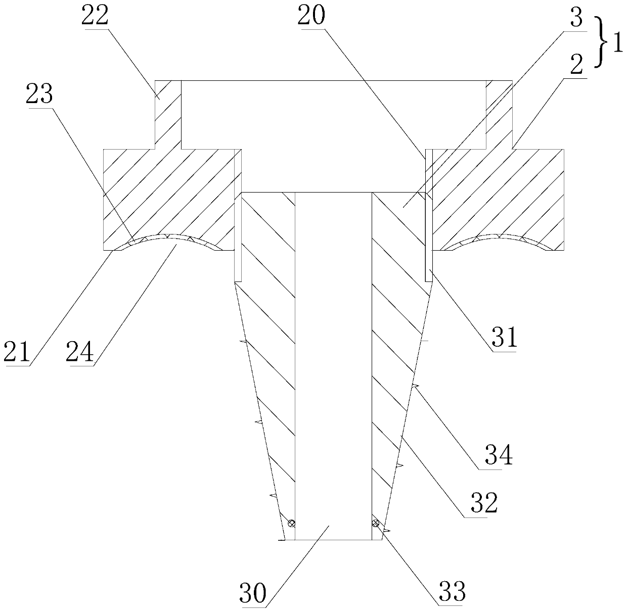
[0018] Such as figure 1 As shown, a grease injection head that is beneficial to filling conductive grease in tension clamps includes a body 1, the body 1 includes an outer sleeve 2 and an inner sleeve 3, and the middle part of the inner sleeve 3 is provided with a grease injection channel 30, so The inner cover 3 includes a connection section 31 connected to the outer cover 2, and a positioning section 32 extending into the tension clamp. The outer cover 2 includes a positioning end surface 21 in contact with the tension clamp, and a section of the main body 1 The fixed head 22 fixed on the grease injection tube, the body 1 is fixed on the tension clamp by means of the positioning section 32 and the positioning end face 21, the conductive grease enters the grease injection channel 30 after passing through the fixed head 22 and is filled to the tension line folder.

[0019] The main body is fixed on the tension clamp through the positioning section and the positioning end face...


PUM


Abstract

The invention relates to a grease injection head facilitating conductive grease filling of a strain clamp. The grease injection head comprises a body. The body includes an outer sleeve and an inner sleeve. A grease injection channel is arranged in the middle portion of the inner sleeve, and the inner sleeve comprises a connecting section and a positioning section. The outer sleeve comprises a positioning end surface and a fixing head, the body is fixed on the strain clamp by the positioning section and the positioning end surface. The grease injection head has the advantages that the body is fixed on the strain clamp by the positioning section and the positioning end surface arranged on the outer sleeve, then conductive grease is injected into the strain clamp through the grease injectionchannel on the inner sleeve, since the positioning section extends into the strain clamp, the conductive grease can be accurately injected into the specified position of the strain clamp, the flowingtime of the conductive grease in the strain clamp is reduced, and the injection efficiency of the conductive grease is improved; and in addition, because the positioning end surface is always in contact with the strain clamp, the mutual sliding between the grease injection head and the strain clamp is effectively avoided, so that the waste phenomenon of the conductive grease in the injection process is reduced, and the working efficiency of the grease injection is improved.

Description

technical field [0001] The invention relates to a grease injecting head which is beneficial for filling conductive grease into tension clamps. Background technique [0002] The compression type strain clamp is used to fix the wire to withstand the tension of the wire, and hang the wire to the metal fitting on the tension string or pole tower. The wire and the strain clamp are connected in the form of crimping. This process often There are multiple axial through holes of 0.5-1.0mm between the single wires in the large cross-section wire. Repeated rainwater intrusion and freezing in the cold make the non-pressing area of ​​the tension clamp gradually bulge until it cracks. In recent years, electric power maintenance During the inspection process, personnel repeatedly found bulging and cracking in the non-pressing area of ​​the tension clamp on the rising side, which seriously threatened the safe operation of the line. [0003] In order to effectively prevent rainwater from in...

Claims


Application Information

Patent Timeline
IPC IPC(8): B05C5/02
CPCB05C5/02
Inventor 汪立锋陈庆吟盛叶弘赵旭阳洪静谈佳栋
Owner ZHEJIANG HUADIAN EQUIP TESTING INST
Learn More