Sampling distribution valve for vehicle particle concentration detector

A particle concentration, sampling distribution valve technology, applied in particle suspension analysis, valve details, multi-port valves, etc., can solve the problems of incomparable detection results, complex distribution valve structure, inaccurate detection results, etc., to reduce particle accumulation. , the effect of reducing the flow time and reducing the turning range

Active Publication Date: 2015-12-16
张家港谱析传感科技有限公司
View PDF4 Cites 1 Cited by
  • Summary
  • Abstract
  • Description
  • Claims
  • Application Information

AI Technical Summary

Problems solved by technology

However, the current concentration detector generally only detects the particle concentration in the same environment, for example, only detects the particle concentration inside the car, or the particle concentration outside the car. The problem lies in the change; the current designers will also think about using the same particle concentration detector to detect two environments, but there are major technical difficulties in it. To detect two environments with the same particle concentration detector, it is necessary to choose to allocate into to the air in the particle concentration detector, so it is necessary to use the distribution valve
However, the distributing valves currently on the market cannot be used for particle concentration detection. The reason is that the structure of the current distributing valves is relatively complicated. After the air containing particulates enters the distributing valve, it is easy to accumulate particulates in the distributing valve. In this way, the air entering the detector The particle content is not consistent with the actual particle content in the corresponding environment, especially the particle content itself is very small, and the signal needs to be amplified in the laser dust concentration sensor, and the error will be amplified by dozens or even hundreds of times, resulting in detection results very inaccurate

Method used


Image

  • Sampling distribution valve for vehicle particle concentration detector
  • Sampling distribution valve for vehicle particle concentration detector
  • Sampling distribution valve for vehicle particle concentration detector

Examples


Embodiment 1

[0020] The orientation described in this embodiment is figure 2 The orientation of the display shown in is determined.

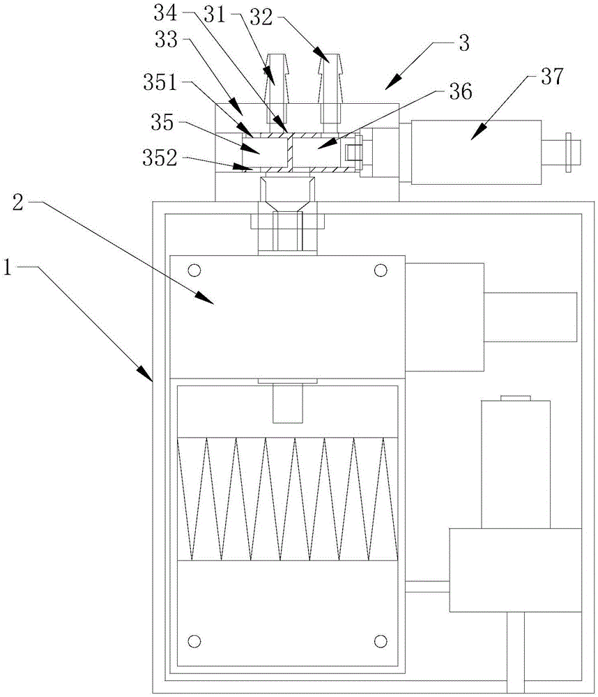
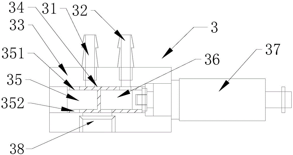
[0021] like figure 1 , 2 As shown, a sampling distribution valve 3 for a vehicle-mounted particulate matter concentration detector 1 includes a valve body 33 and a valve core 34 slidably installed in the inner cavity of the valve body 33. The upper end of the valve body 33 is provided with a high concentration sampling port 31 and low concentration sampling port 32; both the high concentration sampling port 31 and the low concentration sampling port 32 are provided with joints for connecting pipes. The lower end of the valve body 33 is provided with a lead-out port 38; the high-concentration sampling port 31, the low-concentration sampling port 32 and the lead-out port 38 communicate with the inner cavity of the valve body 33; the lead-out port 38 is connected to the dust concentration of the particle concentration detector 1. The inlet of the sensor 2 i...

Embodiment 2

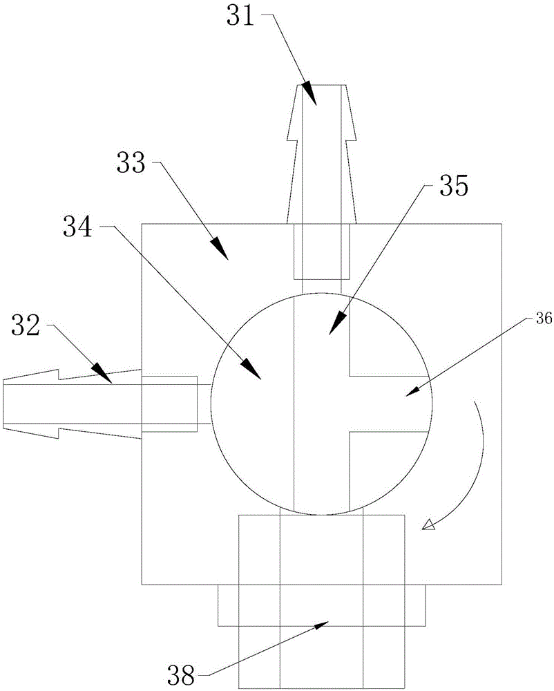
[0023] The orientation described in this embodiment is image 3 The orientation of the display shown in is determined.


PUM


Abstract

The invention discloses a sampling distribution valve for a vehicle-mounted particle concentration detection instrument. The sampling distribution valve comprises a valve body and a valve core, wherein a high-concentration sampling hole, a low-concentration sampling hole and a guide outlet are formed in the valve body and communicated with the inner cavity of the valve body; a high-concentration channel and a low-concentration channel are formed in the valve core; the valve core is driven by a valve core power device to work for butting and communicating the low-concentration sampling hole or the high-concentration sampling hole with the guide outlet; an upper hole and a lower hole of the high-concentration channel are formed in the same vertical position; the high-concentration sampling hole, the upper hole, the lower hole and the guide outlet are vertically and linearly communicated when the high-concentration sampling hole is butted and communicated with the guide outlet by the high-concentration channel. According to the distribution valve, air with particles can be effectively, directly and quickly distributed to a dust concentration sensor of the vehicle-mounted particle concentration detection instrument, particles deposited in the distribution valve are reduced as much as possible, and the accuracy of detection results is improved.

Description

technical field [0001] The invention relates to a sampling distribution valve, in particular to a sampling distribution valve for a vehicle-mounted particulate matter concentration detector. Background technique [0002] Particulate matter concentration detection is a hot topic at present, and it has gradually entered the automotive field. More and more cars need to install on-board particulate matter concentration detectors. The particle concentration detector is a rapid online detection of dust concentration using a laser dust concentration sensor. However, the current concentration detectors generally only detect the concentration of particulate matter in the same environment, for example, only detect the concentration of particulate matter inside the car, or the concentration of particulate matter outside the car. The problem of the change is; the current designers will also think about using the same particle concentration detector to detect two environments, but ther...

Claims


Application Information

Patent Timeline
Patent Type & Authority Patents(China)
IPC IPC(8): F16K11/085F16K31/04G01N15/06
CPCF16K11/078F16K27/041F16K31/04F16K31/50G01N15/06
Inventor 陆耀平丁言闯戚纯波施夏雄
Owner 张家港谱析传感科技有限公司
Why Eureka
Try Eureka