Outage holding relay and drive circuit thereof

A technology for driving circuits and relays, applied in relays, circuits, electrical components, etc., can solve the problems of energy loss, power consumption of relay coils, and control signals are not as easy to use as control signals, so as to reduce power consumption and reduce the flow of electricity. time, the effect of reducing the complexity of use

Inactive Publication Date: 2013-06-19
NANJING UNIV
View PDF4 Cites 1 Cited by
  • Summary
  • Abstract
  • Description
  • Claims
  • Application Information

AI Technical Summary

Problems solved by technology

If the pulse width is not enough, it may cause the relay to fail to switch to the required switching state
In order to ensure the reliable operation of the relay, the pulse width of the control signal is often set to be greater than the actual width of the relay, so that the pulse width exceeding the actual needs will cause the relay coil to consume excess power and cause energy loss.
Moreover, the pulse form control signal in the circuit is not as convenient to use as the DC level control signal.

Method used


Image

  • Outage holding relay and drive circuit thereof
  • Outage holding relay and drive circuit thereof

Examples


Embodiment Construction

[0011] The present invention will be further described below in conjunction with the accompanying drawings.

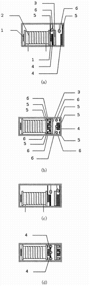
[0012] like figure 1 As shown, the hold relay of the present invention includes an iron core 1 , a coil 2 , a magnet 3 , a fixed iron block 4 , a fixed contact 5 and a movable contact 6 . The coil 2 generates a magnetic field on the iron core 1 after the current passes through it. If the direction of the current in the coil 2 is changed, the direction of the magnetic field will also change to the opposite direction accordingly. Different orientations of the magnetic field will attract or repel the magnet 3 . When the magnet 3 moves to the designated position, it drives the movable contact 6 to move and make contact with the fixed contact 5 or not. A pair of movable contacts and fixed contacts form a switch. When the movable contact is in contact with the corresponding fixed contact or not, the corresponding switch is closed or disconnected. At this time, if there i...


PUM


Abstract

The invention discloses an outage holding relay and a drive circuit thereof. A coil in the outage holding relay enables an iron core to reject or attract a movable magnet through electric currents in different directions, and accordingly movable contact points are driven to move so as to enable a switch to close or open. Two fixed iron pieces in the relay fixedly reach the magnet on a preset position through magnetic force, so that after the switch closes or opens, electricity does not need to be supplied to the coil any longer. The relay detects whether the movable contact points reach preset positions or not by using two switches, and the drive circuit finishes supplying the electricity to the coil of the relay according to a signal. The outage holding relay and the drive circuit thereof can automatically stop supplying the electricity to the coil after the movable contact points reach the preset positions, and therefore energy consumption is reduced. A control signal of the outage holding relay does not need adopting a pulse mode of an existing magnetic holding relay control signal, and therefore the outage holding relay is convenient to use, and furthermore close and open of the switches in the relay can be reliably guaranteed.

Description

technical field [0001] The invention relates to a relay and its drive circuit, in particular to a relay capable of maintaining the switch state when power is off, and a drive circuit used in conjunction with it, which reduces the energy consumed by the relay and is reliable and convenient to control. Background technique [0002] Relays are widely used in various electronic devices due to the advantages of small contact resistance and reliable operation when the switch is closed. At present, electromagnetic relays are mainly used. The electromagnetic relay uses the current flowing through the coil to generate a magnetic field on the iron core to attract or repel the armature to change the switch state. [0003] Common electromagnetic relays on the market require current to flow through the coil to maintain the switch on or off. Relays often consume hundreds of milliwatts or more in this state. The newly appeared magnetic latching relay can maintain the state of the relay ...

Claims


Application Information

Patent Timeline
Patent Type & Authority Applications(China)
IPC IPC(8): H01H47/04
Inventor 方晖张兴敢柏业超孙艳艳
Owner NANJING UNIV
Why Eureka
Try Eureka