Hydraulic pump rotational speed measurement device

A speed measurement and hydraulic pump technology, which is applied to devices using electric/magnetic methods, etc., can solve the problem of no hydraulic pump speed measurement device, etc., and achieve the effect of simple structure and convenient installation.

Inactive Publication Date: 2013-03-13
SHANGHAI ELECTRICAL HYDRAULICS & PNEUMATICS
View PDF6 Cites 8 Cited by
  • Summary
  • Abstract
  • Description
  • Claims
  • Application Information

AI Technical Summary

Problems solved by technology

[0003] However, so far, there has not been a hydraulic pump speed measuring device that can be directly installed in the hydraulic pump to monitor the hydraulic pump speed.

Method used


Image

  • Hydraulic pump rotational speed measurement device
  • Hydraulic pump rotational speed measurement device

Examples


Embodiment Construction

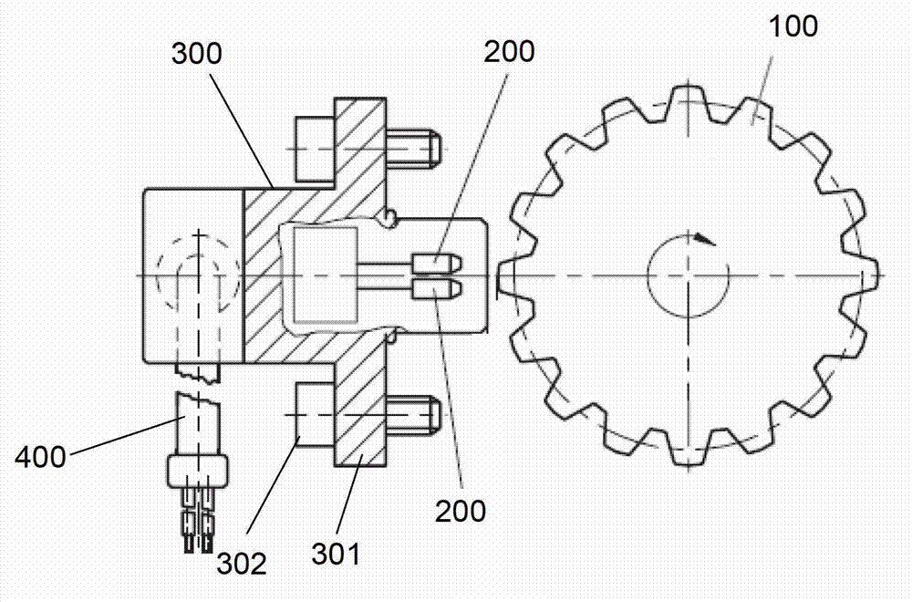
[0015] like figure 1 As shown, the hydraulic pump rotational speed measuring device of the present invention includes a magnetic gear 100 , a Hall effect element 200 , a housing 300 and a cable 400 .

[0016] Wherein, the Hall effect element 200 is located beside the magnetic gear 100 and aligned with the magnetic gear 100 along the radial direction of the gear. One end of the casing 300 has an opening covering the Hall effect element 200 , the opening faces the magnetic gear 100 , and the cable 400 passes through the rear end (the other end) of the casing. Both sides of the housing 300 have fixing ears 301 , and fixing bolts 302 are arranged on the fixing ears 301 .

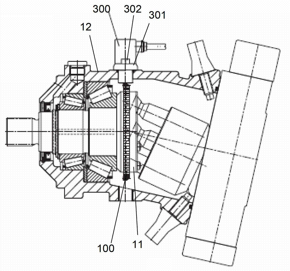
[0017] In order to be conveniently installed on the rotary body inside the hydraulic pump, combined with figure 2 As shown, the magnetic gear 100 is preferably a ring gear.

[0018] like figure 2 As shown, a kind of installation mode of the present invention in hydraulic pump is as follows:

[0019] The r...


PUM


Abstract

The invention discloses a hydraulic pump rotational speed measurement device which is formed by a magnetic gear and a Hall effect element located beside the magnetic gear and radially aligning at the magnetic gear along the magnetic gear, and a cable is connected onto the Hall effect element. The hydraulic pump rotational speed measurement device has the advantages of being simple in structure, convenient to install and capable of being directly installed on a hydraulic pump to monitor hydraulic pump rotational speed.

Description

technical field [0001] The invention belongs to the technical field of rotational speed sensors, in particular to a rotational speed sensor for hydraulic pumps. Background technique [0002] Hydraulic pumps (or motors) are mainly used for hydraulic drive of walking machinery. Traditional hydraulic pumps / motors mainly include housings, end covers and rear covers fixed at the front and rear ends of the housings, and motor shafts and plungers inside the housings. Components, mandrel, cylinder block, and distribution plate; one end of the motor shaft protrudes from the end cover, and the other end is provided with a ball and socket plate. The plunger component is composed of a connecting rod and a plunger. The connecting rod is composed of a large ball head, a small ball head and The connecting rod connecting the big and small ball heads is integrally formed, the big ball head of the connecting rod is set in the ball socket plate, the plunger has a plug hole, and there is a ball...

Claims


Application Information

Patent Timeline
Patent Type & Authority Applications(China)
IPC IPC(8): G01P3/44
Inventor 陈俊龙李斌
Owner SHANGHAI ELECTRICAL HYDRAULICS & PNEUMATICS
Why Eureka
Try Eureka