
Rock perforating machine with drill bit convenient to replace

A punching machine and drill bit technology, which is applied in the field of punching machines, can solve problems such as rod shaking, easy deviation of the device, and the inability of users to drill holes accurately, so as to improve quality and work efficiency.

Inactive Publication Date: 2021-01-15
广州郝舜科技有限公司
View PDF0 Cites 0 Cited by
  • Summary
  • Abstract
  • Description
  • Claims
  • Application Information

AI Technical Summary

Problems solved by technology

[0004] 1. The structure of the rock drilling machine is relatively simple, lacking a quantitative structure, and the user cannot accurately drill holes with a preset depth
[0005] 2. The existing device lacks a guiding structure, which causes the device to easily deviate during the drilling process, which affects the quality of drilling
[0006] 3. In the process of drilling rocks in the existing drilling machine, the drill bit is prone to damage. The general drill bit is welded on the device, which is inconvenient for the user to disassemble and affects the replacement speed of the device.
[0007] 4. During the rotation of the rotating rod of the existing punching machine, the rod shakes due to the excessive speed, which affects the quality of punching

Method used


Image

  • Rock perforating machine with drill bit convenient to replace
  • Rock perforating machine with drill bit convenient to replace
  • Rock perforating machine with drill bit convenient to replace

Examples


Embodiment Construction

[0051] The following will clearly and completely describe the technical solutions in the embodiments of the present invention with reference to the accompanying drawings in the embodiments of the present invention. Obviously, the described embodiments are only some, not all, embodiments of the present invention. Based on the embodiments of the present invention, all other embodiments obtained by persons of ordinary skill in the art without making creative efforts belong to the protection scope of the present invention.

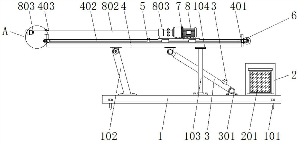
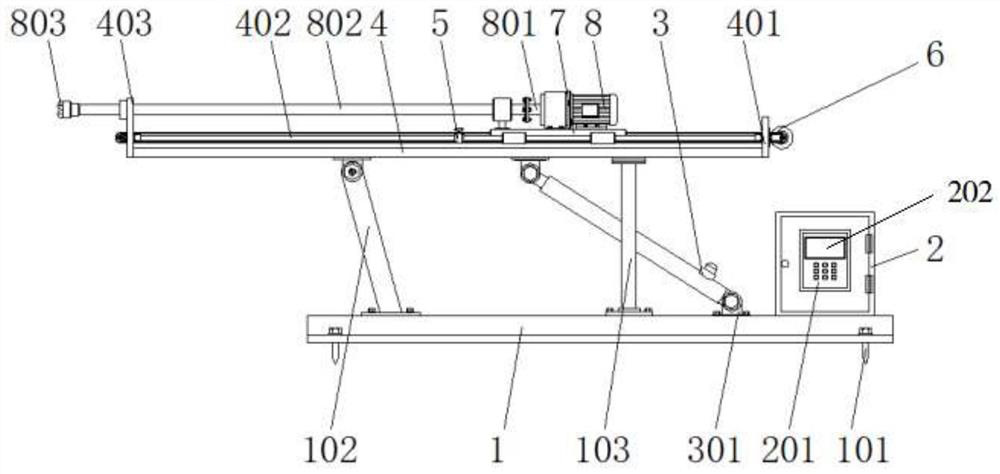
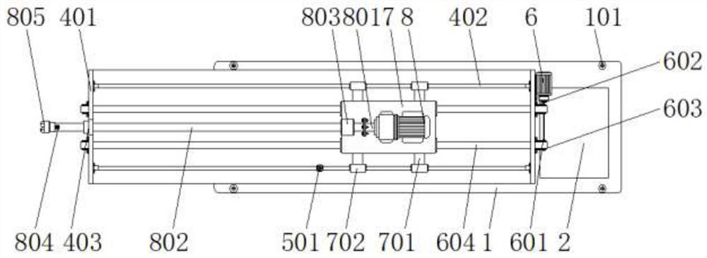
[0052] see Figure 1-5 , an embodiment provided by the present invention: a rock drilling machine for easy replacement of drill bits, including a base 1, a hydraulic push rod 3 and a support plate 4, the top of the base 1 is welded with a control box 2, and the base 1 is fixed on On the ground, it is used to support the electric control box 2 and improve the stability of the electric control box 2. The top of the base 1 is movably connected to the hydraulic pu...


PUM


Abstract

The invention discloses a rock perforating machine with a drill bit convenient to replace. The rock perforating machine comprises a base, a hydraulic push rod and a supporting plate, wherein an electric control box is welded to the top of the base, the top of the base is movably connected to the hydraulic push rod through a connecting piece, and the top end of the hydraulic push rod is movably connected to the supporting plate through a bolt, mounting plates are mounted on the two sides of the supporting plate, guide rings are arranged at the tops of the mounting plates, a control motor is mounted on one sides of the mounting plates through bolts, supporting sliding rods are mounted on the inner sides of the mounting plates through bolts, limiters are mounted on the outer sides of the supporting sliding rods, and tightening pieces are mounted at the tops of the limiters in a penetrating mode. According to the machine, limiting stoppers are installed on the outer sides of the supportingsliding rods, a user presets a needed depth of a large hole, then the tightening pieces are moved to designated positions, the limiting stoppers are fixed through the tightening pieces, the limitingstoppers re used for stopping in a perforating process, and the drilling accuracy is guaranteed.

Description

technical field [0001] The invention relates to the technical field of drilling machines, in particular to a rock drilling machine which facilitates the replacement of drill bits. Background technique [0002] The rock drilling machine is a relatively important tool in the mining process. It drills holes in the rock to facilitate the installation of various equipment in the later stage and facilitate the mining of ore. [0003] The defective that existing rock drilling machine exists is: [0004] 1. The structure of the rock drilling machine is relatively simple, lacking a quantitative structure, and the user cannot accurately drill holes with a preset depth. [0005] 2. The existing device lacks a guiding structure, which causes the device to easily deviate during the drilling process, which affects the quality of drilling. [0006] 3. In the process of drilling rocks in existing drilling machines, the drill bit is prone to damage. The general drill bit is welded on the d...

Claims


Application Information

Patent Timeline
Patent Type & Authority Applications(China)
IPC IPC(8): E21B15/00E21B3/02E21B44/04E21B44/02E21B19/24E21B17/02
CPCE21B3/02E21B15/003E21B17/02E21B19/24E21B44/02E21B44/04
Inventor 陈美随
Owner 广州郝舜科技有限公司
Learn More