Method for monitoring a chain hoist and chain hoist

A pulley block and chain technology, applied in the direction of engine control, clockwork mechanism, portable lifting device, etc., can solve the problems of not being able to identify the deviation of the motor speed, and achieve the effects of avoiding thermal overload, reducing wear, and avoiding falling

Active Publication Date: 2009-09-23
KONECRANES GLOBAL
View PDF8 Cites 0 Cited by
  • Summary
  • Abstract
  • Description
  • Claims
  • Application Information

AI Technical Summary

Problems solved by technology

The monitoring is carried out here by processing the two speed signals of the two speed sensors. With this monitoring device, it is not possible to detect the speed deviation of the motor and its operating data in the sense of too high or too low speed.

Method used


Image

  • Method for monitoring a chain hoist and chain hoist

Examples


Embodiment Construction

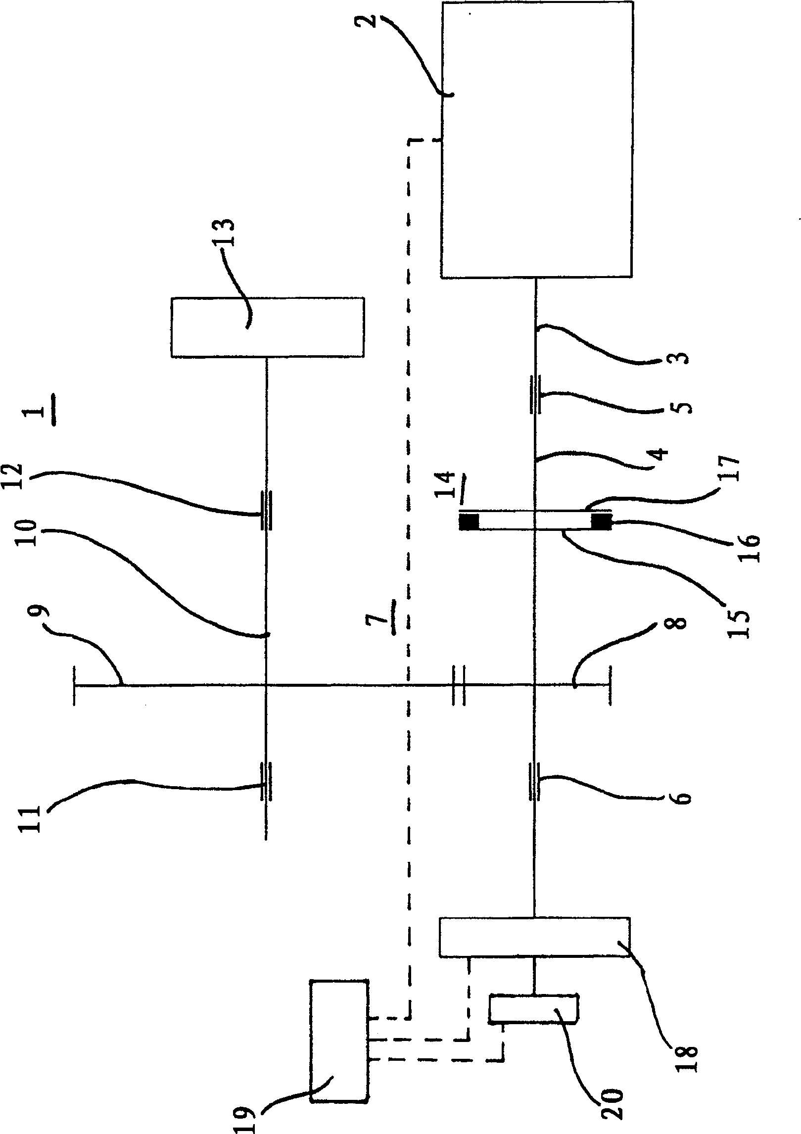
[0023] The chain blocks 1 have a drive motor 2 each having a motor shaft 3 protruding from the output of the drive motor 2 . The motor shaft 3 is arranged concentrically with the gearbox input shaft 4 and is connected to it in a rotationally fixed manner. The transmission input shaft 4 is supported in its end region by a first bearing 5 and a second bearing 6 , in particular designed as rolling bearings. The gearbox input shaft 4 is a component of the gearbox 7, which is designed as a single-stage in the exemplary embodiment shown, but can also be designed as a multi-stage. Gearbox 7 is mainly made up of gearbox input shaft 4, and a first gear 8 is installed between its bearings 5 ​​and 6, and it meshes with a second gear 9. The second gearwheel 9 of the single gear stage of the gearbox 7 is mounted non-rotatably on the gearbox output shaft 10, the second gearwheel 9 is supported on both sides by a third bearing 11 and a fourth bearing 12, in particular designed as rolling be...


PUM


Abstract

The invention relates to a method for monitoring a chain block block and a chain block block, the drive motor of which is connected to a gearbox (14) at the output end through a slip clutch (14). In order to achieve a reliable operation mode of the chain block block, the present invention proposes to measure the speed of the gearbox (7) through the sensor (18), and the measured speed of the gearbox is communicated in the control device (19) with the speed of the drive motor (2). The operating speed of the drive motor (2) determined from the operating data is compared and the speed of the gearbox (7) and the operating speed are determined, taking into account tolerances and, if necessary, the transmission ratio of the gearbox (7). Switch off the drive motor (2) when there is a deviation.

Description

technical field [0001] The invention relates to a method for monitoring a chain block which has a drive motor which is connected at the output to a gearbox via a slip clutch. The invention also relates to a chain pulley block, the chain block block has a drive motor, and the drive motor is connected to a gearbox through a sliding clutch at the output end. Background technique [0002] A chain block with a drive motor is known from German patent DE 199 27 847 C1. The motor shaft is connected with the input shaft of the gearbox through a slip clutch. An electromagnetically controllable disc brake is provided on the end of the transmission input shaft opposite to the drive motor. [0003] Common chain blocks are also known, the brake of which is arranged on the output shaft of the drive motor so as to precede the slipping clutch. [0004] In chain blocks of this type, overloading of the block block, failure of the end switch or non-release of the brake as a functional error ...

Claims


Application Information

Patent Timeline
Patent Type & Authority Patents(China)
IPC IPC(8): B66D1/54B66D3/18B66D1/48B66D3/22
CPCB66D3/22Y10T477/363Y10T477/759Y10T477/393Y10T477/35B66D1/54B66D1/485Y10T477/747
Inventor 霍尔格·弗赖塔格奥利弗·莫尔埃里克·阿佩尔拉尔夫·艾辛乌多·格塞姆斯基布克哈德·哈泽纳克安东·明策布洛克朱利亚诺·佩尔西科
Owner KONECRANES GLOBAL
Why Eureka
Try Eureka