Vivaldi antenna array

An antenna array and antenna technology, applied in the direction of antenna array, antenna, resonant antenna, etc., to achieve the effect of simple structure, easy production, and small size

Active Publication Date: 2015-04-22
UNIV OF ELECTRONICS SCI & TECH OF CHINA
View PDF3 Cites 0 Cited by
  • Summary
  • Abstract
  • Description
  • Claims
  • Application Information

AI Technical Summary

Problems solved by technology

[0003] The purpose of the present invention is to propose a Vivaldi antenna array in order to solve the contradiction between the ultra-wideband and miniaturization of the existing Vivaldi antenna

Method used


Image

  • Vivaldi antenna array
  • Vivaldi antenna array
  • Vivaldi antenna array

Examples


Embodiment Construction

[0012] In order to facilitate the understanding of those skilled in the art, the present invention will be further described below in conjunction with the accompanying drawings and specific embodiments:

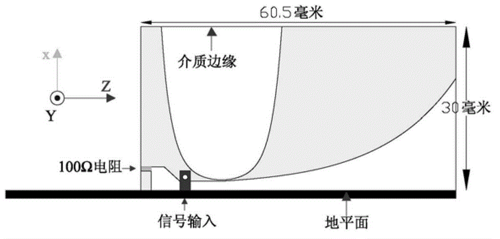
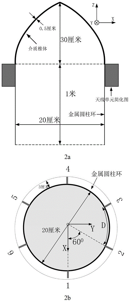
[0013] The Vivaldi antenna array of the present invention specifically includes: an even number of Vivaldi antennas, metal post rings, dielectric cones and SMA connectors, wherein the even number of Vivaldi antennas are evenly and vertically arranged on the shell of the metal post ring, each The antenna unit is connected with an SMA connector to form a multi-port feed array structure; the dielectric cone is placed on the top of the metal post ring; the SMA connector is placed on the inner wall of the metal post ring, and the inner core passes through the metal post and the Vivaldi antenna One end of the feedback microstrip line is connected, the shell is connected to the metal post ring, and the other end of the feedback microstrip line is connected to the ground plane of the ...


PUM


Abstract

The invention discloses a Vivaldi antenna array which specifically comprises an even number of Vivaldi antennas, metal column rings, medium cones and sub-miniature-A (SMA) connectors. The even number of Vivaldi antennas are evenly and vertically arranged on casings of the metal column rings. The medium cones are arranged at the top ends of the metal column rings. The SMA connectors are placed on inner walls of the metal column rings, cores penetrate through the metal column rings to be connected with one end of a feedback microstrip line of each Vivaldi antenna, the other end of each feedback microstrip line is connected with a ground plane of the antennas through a metallized through hole, and the casings are connected with the metal column rings. The antenna array adopts monopolar Vivaldi antennas as antenna units, a resistor is integrated to the tail end of each antenna, and the characteristics of miniaturization and broadband are achieved. Due to the fact that a monopolar structure is adopted, the reflecting influence of the medium cones on aerial radiation electromagnetic waves is small, and end-on-fire performance is kept.

Description

technical field [0001] The invention belongs to the technical field of electromagnetic fields and antennas, and in particular relates to the design of a broadband miniaturized Vivaldi antenna. Background technique [0002] The Vivaldi antenna is an end-fire traveling wave antenna proposed by Gibson, which consists of a transition from a narrower slot line to a wider slot line. The groove line changes exponentially, and the width of the groove line on the dielectric plate is gradually increased to form a bell mouth that radiates outward or receives electromagnetic waves inward. At different frequencies, its different parts emit or receive electromagnetic waves, and the electrical length of each radiation part relative to the wavelength of the corresponding different frequency signals is constant, so theoretically speaking, it has a wide frequency band. However, due to some limitations in its design, for example, the length of its radial slot line should be greater than λ 0 ...

Claims


Application Information

Patent Timeline
Patent Type & Authority Patents(China)
IPC IPC(8): H01Q1/12H01Q9/30H01Q13/08H01Q21/00H01Q23/00
Inventor 文光俊王平
Owner UNIV OF ELECTRONICS SCI & TECH OF CHINA
Why Eureka
Try Eureka