
Adapter for clamping device

A technology of clamping device and adapter, applied in the direction of clamping/spring connection, connection, electrical components, etc., can solve the problems of cable fixing, sliding out, etc.

Inactive Publication Date: 2016-08-03
SIEMENS AG
View PDF3 Cites 0 Cited by
  • Summary
  • Abstract
  • Description
  • Claims
  • Application Information

AI Technical Summary

Problems solved by technology

If, for example, a cable with a much smaller cross-section should now be clamped into such a clamping device, there is the danger that the cable cannot be secured by the height-variable clamping plate and that will slide out of the clamp connection

Method used


Image

  • Adapter for clamping device
  • Adapter for clamping device
  • Adapter for clamping device

Examples


Embodiment Construction

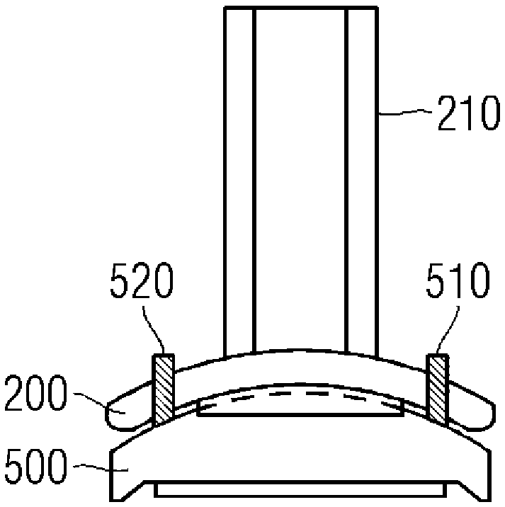
[0021] figure 1 A clamping device 100 for electrically connecting cables or wires is shown. With regard to its structure, the clamping device 100 is formed by a base body 110 which typically consists of a bent strip made of C30 or C45 steel, high-grade steel or brass. The base body 110 has an opening with a height T and a width W, through which cables or wires can be put into the base body 110 . The base body 110 has a depth L. As shown in FIG. exist figure 1 In , the cable or wire is outlined with a circular cross-section U with a diameter D. Furthermore, the clamping device 100 has a height-variable clamping plate 200 and a contact 300 . If cables or wires are put into the base body, the height-adjusting mechanism 210 connected to the height-variable clamping plate 200 can make the clamping plate 200 from the open position according to the screw movement of the height adjustment mechanism 210. figure 1 The illustration in - towards the contact 300 movement. This causes...


PUM


Abstract

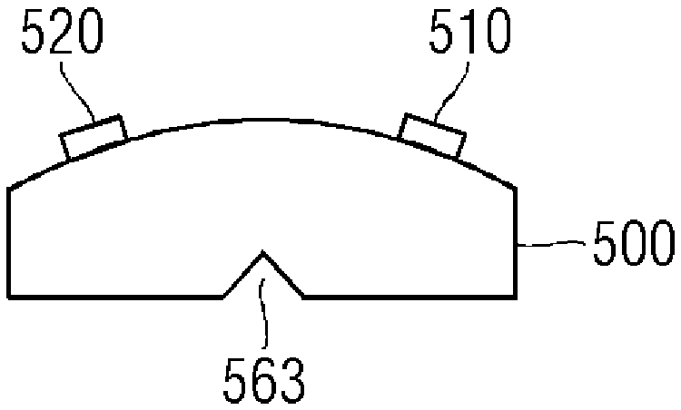
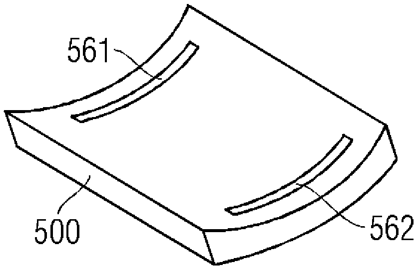
The invention proposes an adapter for a clamping device for electrically connecting cables or wires, wherein the clamping device comprises electrical contacts and a height-variable splint, wherein the The clamping plate is designed to mechanically press the cable or line against the electrical contacts of the clamping device, and the adapter is designed to be fixable on the clamping plate of the clamping device , so that the cross-section of the cable to be clamped or the wire to be clamped can be matched by the adapter, and the height stroke of the height-variable clamping plate of the clamping device can be matched by the adapter Adaptation or adjustment of the width of the clamping plates can be carried out by means of the adapter.

Description

technical field [0001] The invention relates to an adapter for a clamping device. Background technique [0002] Terminals are generally known in electronics, which are used to releasably connect cables, wires, conductors to each other or to devices or to releasably connect them. The clamping device ensures a permanent and safe electrical contact. Electrical contact is achieved by mechanically fixing the connected cables, wires or conductors in the electrically conductive body by means of bolts or springs. The clamping device can likewise be attached to electrical devices so that they can be electrically contacted by means of cables or lines. [0003] Housings such as circuit breakers, which can typically switch currents from 10A to 100A and more, include such clamping devices. The individual phases of the current are typically switched individually, for example in so-called pole boxes. A movable contact and a fixed contact are accommodated in the pole box, and the movabl...

Claims


Application Information

Patent Timeline
Patent Type & Authority Patents(China)
IPC IPC(8): H01R4/28H01R4/40
CPCH01R4/363H01R4/44
Inventor O.豪斯纳C.梅奇尔
Owner SIEMENS AG
Learn More