Electronic component cooling unit and power converting device

一种电力变换装置、电子部件的技术,应用在电气设备构造零部件、输出功率的转换装置、电气元件等方向,能够解决高额成本及制作时间、无法容易地变更制冷剂供给口及排出口的配置等问题

Inactive Publication Date: 2013-03-13
YASKAWA DENKI KK
View PDF7 Cites 5 Cited by
  • Summary
  • Abstract
  • Description
  • Claims
  • Application Information

AI Technical Summary

Problems solved by technology

[0005] However, in the structure of the above-mentioned prior art, since the first and second housings are generally produced by a die-casting process of pressing molten metal into a mold, in order to change the arrangement of the supply port and the discharge port according to various needs, Need to change the mold
Therefore, high cost and production time are required, and there is a problem that the arrangement of the supply port and the discharge port of the refrigerant cannot be easily changed.

Method used


Image

  • Electronic component cooling unit and power converting device
  • Electronic component cooling unit and power converting device
  • Electronic component cooling unit and power converting device

Examples


Embodiment Construction

[0021] Hereinafter, embodiments will be described with reference to the drawings. In addition, in this embodiment, the case where the electronic component cooling module is applied to the power conversion apparatus which converts from alternating current to direct current or from direct current to alternating current is demonstrated as an example.

[0022]

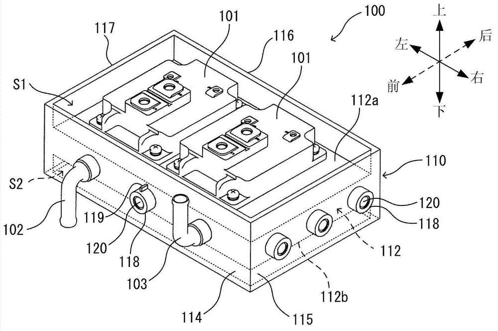
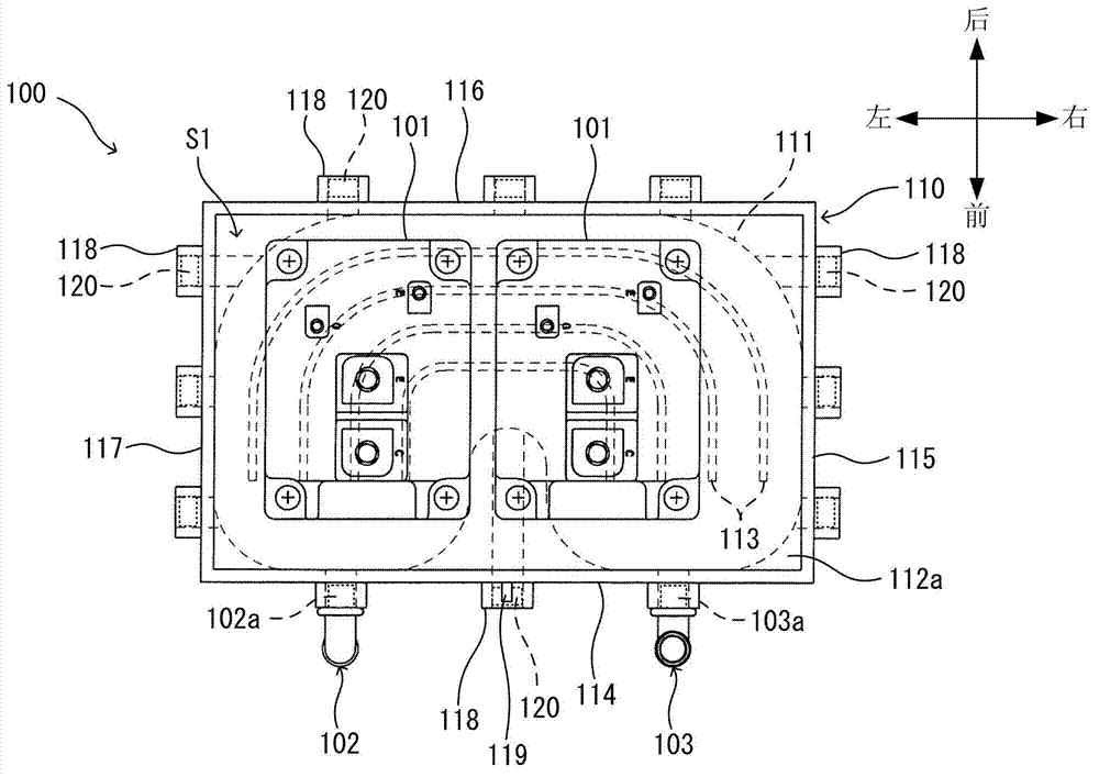
[0023] use figure 1 and figure 2 The overall configuration of the first power conversion device 100 will be described. In addition, for the convenience of description, the direction is set as follows. That is, will figure 1 Middle left direction ( figure 2 middle and bottom direction) to "Front", set the figure 1 middle upper right direction ( figure 2 center and upper direction) to "Back", set the figure 1 Middle left direction ( figure 2 center-left direction) to "Left", set the figure 1 Bottom right direction ( figure 2 center-right direction) to "Right", set the figure 1 upper middle direction ( fig...


PUM


Abstract

An electronic component cooling unit includes a housing having a flow path in an interior thereof, the flow path being configured to circulate a cooling medium; two surfaces, that is, a top surface and a bottom surface, provided at the housing and to which electronic components are mounted; side surfaces provided at the housing and surrounding the top surface and the bottom surface; a plurality of opening portions provided at the side surfaces and communicating with the flow path; and a closing member closing, among the plurality of opening portions, the opening portion or each opening portion other than the opening portions corresponding to a supply opening and a discharge opening for the cooling medium.

Description

technical field [0001] Embodiments disclosed in the present invention relate to an electronic component cooling assembly and a power conversion device. Background technique [0002] Patent Document 1 describes a structure for separately sealing a housing chamber housing electronic components and a cooling passage formed in a structural body for cooling the electronic components. In this electronic component cooling unit (electronic component housing structure), the first and second housings each forming a housing chamber for housing electronic components are joined at joint surfaces, and a flow channel area and a communication channel area are formed on the joint surfaces. The cooling channel through which the cooling liquid flows passes through the flow channel area, the communication channel connecting the storage chambers of the first and second casings passes through the communication channel area, and an integrally formed sealing member is arranged on the joint surface,...

Claims


Application Information

Patent Timeline
Patent Type & Authority Applications(China)
IPC IPC(8): H05K7/20H02M7/00
CPCH05K7/20927H01L23/473F28F27/00H05K7/20H01L2924/0002H01L2924/00
Inventor 长尾敏男伊藤徹也
Owner YASKAWA DENKI KK
Why Eureka
Try Eureka