Laser scanning apparatus and method of use

A technology of laser scanning and equipment, applied in the field of measuring beam scanning system and laser scanning system

Inactive Publication Date: 2013-03-13
RENISHAW PLC
View PDF4 Cites 58 Cited by
  • Summary
  • Abstract
  • Description
  • Claims
  • Application Information

AI Technical Summary

Problems solved by technology

But none offer variable laser angle scanning capability

Method used


Image

  • Laser scanning apparatus and method of use
  • Laser scanning apparatus and method of use
  • Laser scanning apparatus and method of use

Examples


Embodiment Construction

[0069] While the invention is susceptible to various modifications and alternative forms, specific embodiments have been shown by way of example in the drawings and will now be described in detail. It should be understood, however, that the invention is not intended to be limited to the particular forms disclosed. On the contrary, the invention is to cover all modifications, equivalents and alternatives falling within the spirit and scope of the invention as defined by the appended claims.

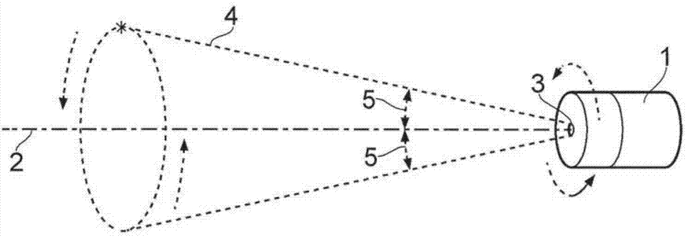
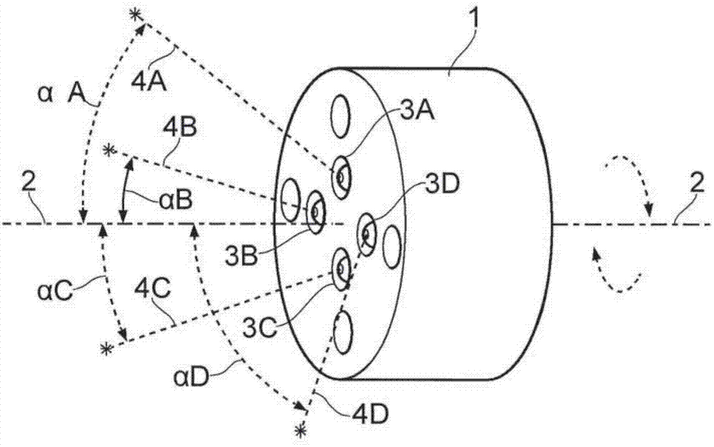
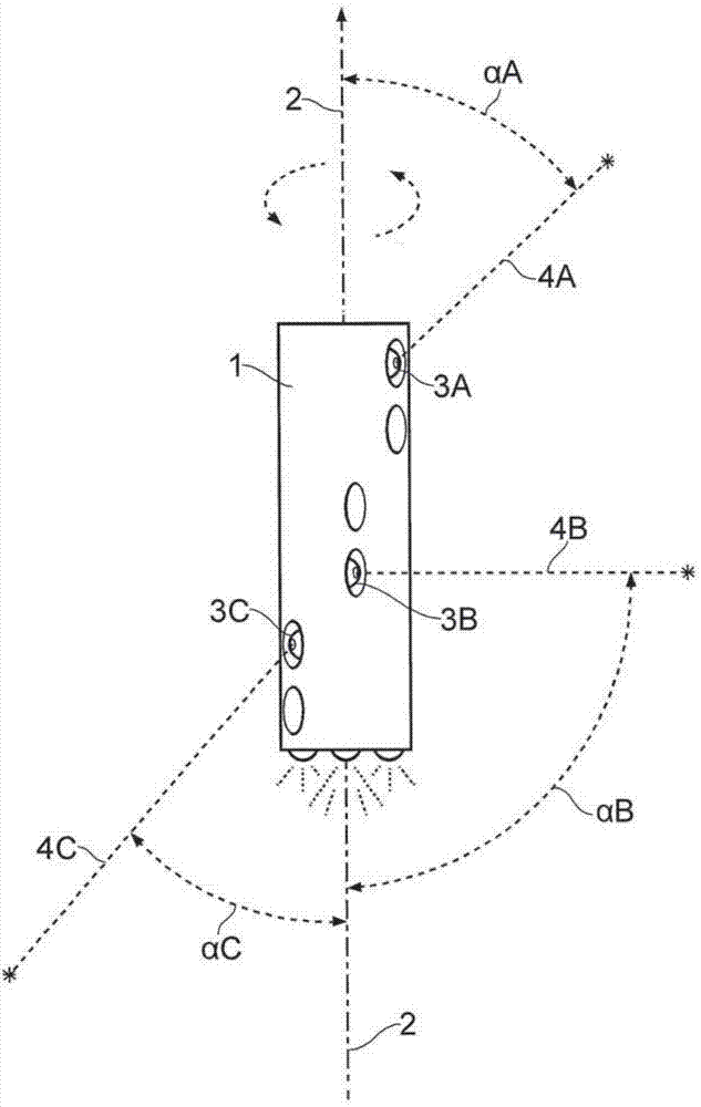
[0070]A novel cone scanning laser system and method of use are provided. "Conical scanning" is the term used herein with reference to a method of operating a laser scanning system in which, as described in accordance with some embodiments, the laser is positioned at an angle within, for example, a rotating housing such that the path of the laser beam is within the The housing forms a cone when rotated about its axis of rotation. The system does not necessarily include a tilt mechanism, t...


PUM


Abstract

A laser system comprises a housing and a laser. The laser can be positioned in the housing such that its laser beam is transmitted at an angle and its path forms a cone as the housing rotates. The laser device may also contain two or more lasers, the angle of each laser may be the same or different, and the angular position of each laser may be fixed or variable. The laser system may be stationary or mobile and used in a variety of methods to detect an object or topography and produce a three dimensional image. That information can be further used to provide maps, terrain data, volumetric measurements, landing guidance, obstacle avoidance warnings, mining profiles and other useful material.

Description

technical field [0001] The invention relates to the field of measuring beam scanning systems, more preferably the invention relates to the field of laser scanning systems. Background technique [0002] Various measurement beam scanning systems are available for inspection or measurement. For example, Measurement Device Ltd. has marketed the Cavity Automatic Scanning Laser System (C-ALS), which is used to measure inaccessible voids or cavities, such as for potential Underground caverns for mining operations. The C-ALS has a laser head that is rotated by a pan-tilt mechanism. The laser head can be attached to a telescoping boom and lowered into the cavity through the access borehole. The laser scans the cavity as it is rotated and angled by the pan-tilt mechanism, producing a detailed 3D representation of the cavity. [0003] Another system uses a continuous survey laser directed vertically and horizontally, usually by motorized means, to vector scan surrounding objects or...

Claims


Application Information

Patent Timeline
Patent Type & Authority Applications(China)
IPC IPC(8): G02B26/10G01P13/02G01S17/10G01S17/95G05D1/06G01S17/89
CPCG01S17/42G01C11/025G01S17/89F21V21/002G02B26/108G01S7/4815G01C15/002G01S7/4817
Inventor 斯蒂芬·莱斯利·鲍尔
Owner RENISHAW PLC
Why Eureka
Try Eureka