Pole group shaping device for battery clamp

A technology for shaping devices and battery fixtures, which is applied to battery pack components, circuits, electrical components, etc., and can solve problems such as weakening of the force

Active Publication Date: 2013-03-20
ZHEJIANG HAIYUE AUTOMATIC MACHINERY
View PDF8 Cites 13 Cited by
  • Summary
  • Abstract
  • Description
  • Claims
  • Application Information

AI Technical Summary

Problems solved by technology

[0003] In the patent No. "201010128749.6", the patent titled "Automatic Ear Mold" discloses a set of devices for arranging ears, including a mold base, a shaping mechanism, and a push plate device located above the shaping mechanism. The plate mechanism is connected by an elastic mechanism. There are horizontally movable shaping grooves arranged in the shaping mechanism. The pushing plate mechanism pushes the shaping mechanism to move through the elastic mechanism so that the product tab enters the shaping groove. When the pushing plate mechanism goes down, it acts on the shaping groove. The mechanism shrinks the shaping groove laterally to realize the shape of the tab. This scheme improves the efficiency of the whole ear without damaging the tab. However, the thrust generated by the push plate mechanism needs to be transformed into the side edge of the tab through the coordinated movement of the push plate and the inclined surface between the movable clip. The vertical force, the conversion of the thrust will weaken the final force. To make the transformed thrust perpendicular to the tab, it is necessary to ensure high precision in manufacturing and installation. If there is a deviation, it may cause the tilt of the plate

Method used


Image

  • Pole group shaping device for battery clamp
  • Pole group shaping device for battery clamp

Examples


Embodiment Construction

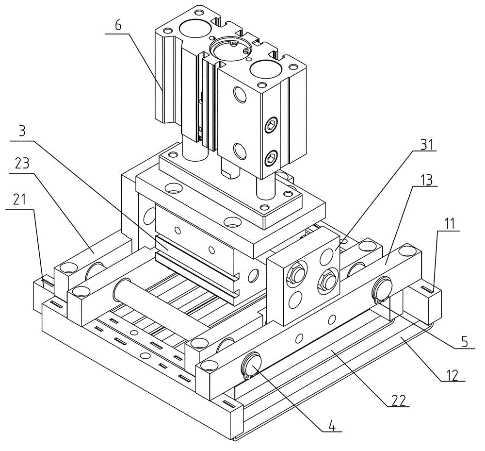
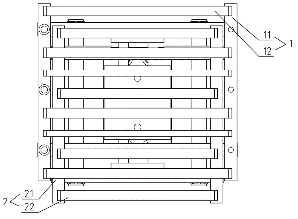
[0019] refer to figure 1 and figure 2 , which shows an electrode group shaping device for battery clamps according to the present invention, including a first bracket 1, a second bracket 2 and a driving device 3, and the first bracket 1 and the second bracket 2 are provided with a number of shaping devices in the same direction. strips, and the shaping strips 12 of the first bracket and the shaping strips 22 of the second bracket are arranged in parallel with each other, and the shaping strips 22 of the second bracket are arranged between the shaping strips 12 of two adjacent first brackets, and the shaping strips 22 of the pole plates The tabs pass between the shaping strips, and the driving force of the driving device causes the first bracket and the second bracket to move relative to each other. When the shaping strips are approaching each other, the tabs are used to straighten the tabs into the same straight line. Realize the shaping of the pole group in the fixture.

...


PUM


Abstract

The invention relates to a pole group shaping device for a battery clamp. The pole group shaping device comprises a first support, a second support and a driving device, wherein a plurality shaping strips are arranged on the first support and the second support in the same direction, and the shaping strips on the first support and the shaping strips on the second support are arranged at intervals; and the relative movement between the first support and the second support is generated by the driving force of the driving device. Electrode lugs penetrate between the shaping strips, the relative movement between the first support and the second support is generated by the driving force of the driving device, and the shaping strips between which the distance becomes small clamp the electrode lugs, so that the electrode lugs are arranged in a straight line, and thus the shaping of the pole group in the battery clamp is realized.

Description

technical field [0001] The invention relates to a pole group shaping device for a battery clamp. Background technique [0002] In the traditional battery production process, the two processes of tab correction and shaping are all carried out manually. There are certain deficiencies in this kind of manual operation mode. The first is low work efficiency, and the second is unstable quality. The specific operation process is as follows: the lug inserting process, after the workers insert the assembled pole group into the mold box, hold a correction plate to press the pole group in place, and then put the correction plate into the pole group to fix the position; In the tab calibration process, another correction plate is used to correct the tabs, and finally the locking wrench of the mold box is locked by hand; in the tab shaping process, after the mold box is locked, the worker takes pliers to lock the outside of the pole group. The negative ear is reshaped. [0003] In the...

Claims


Application Information

Patent Timeline
Patent Type & Authority Applications(China)
IPC IPC(8): B21D1/00H01M2/26
CPCY02E60/12Y02E60/10
Inventor 林雁斌张建章
Owner ZHEJIANG HAIYUE AUTOMATIC MACHINERY
Why Eureka
Try Eureka