De-burring device for wheel

A technology for deburring and wheel removal, which is applied in the direction of grinding machines, metal processing equipment, grinding/polishing equipment, etc. It can solve the problems of poor burr treatment effect at the corner of the flange, adverse effects of the motor, and low speed of the center line of the brush. , to achieve the effect of avoiding frequent commutation, good removal effect, and avoiding low center line speed

Active Publication Date: 2015-04-01
CITIC DICASTAL
View PDF9 Cites 0 Cited by
  • Summary
  • Abstract
  • Description
  • Claims
  • Application Information

AI Technical Summary

Problems solved by technology

[0003] In the wheel deburring device in the prior art, the centerline speed of the brush is low, and the burr treatment effect at the corner of the flange is not good, and the disc brush frequently changes direction when brushing burrs, which has an adverse effect on the motor

Method used


Image

  • De-burring device for wheel
  • De-burring device for wheel
  • De-burring device for wheel

Examples


Embodiment Construction

[0022] The details and working conditions of the specific device proposed according to the present invention will be described below in conjunction with the accompanying drawings.

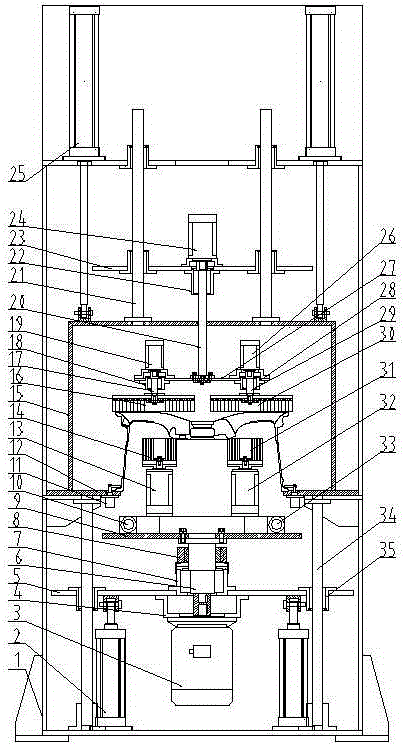
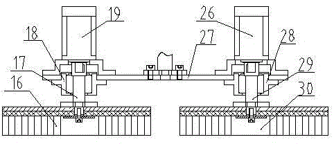
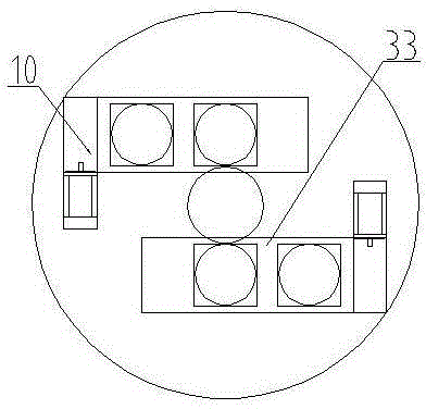
[0023] The wheel deburring device of the present invention consists of a frame 1, a lifting cylinder 2, a lower motor 3, a connecting frame 4, a lower plate 5, a shaft 6, a bearing seat 7, a conductive slip ring 8, a lower plate 9, a servo Sliding table one 10, corner cylinder 11, positioning plate 12, lower motor two 13, lower brush one 14, dust cover 15, upper brush one 16, shaft two 17, bearing seat two 18, upper motor two 19, shaft Three 20, upper guide column 21, bearing seat three 22, upper plate one 23, upper motor one 24, lifting cylinder 25, upper motor three 26, upper plate two 27, bearing seat four 28, shaft four 29, upper brush two 30, following hairbrush two 31, following motor three 32, servo slide table two 33, following guide column 34, following guide sleeve 35 and upper feed cylin...


PUM


Abstract

The invention discloses a de-burring device for a wheel. The de-burring device comprises a frame, an air cylinder, a motor, a corner cylinder and the like. Two lower hairbrushes auto-rotate at the same rotation speed and in different rotation directions and are driven to orbit by a lower motor I at the same time; and similarly, two upper hairbrushes auto-rotate at the same rotation speed and in different rotation directions and are driven to orbit by an upper motor I at the same time. When the de-burring device is used, the automatic rotating hairbrushes can be in contact with all parts capable of being brushed on a rear cavity of the wheel at the respective maximum linear speed; and the problems of low linear speed of the center hairbrushes and poor de-burring effect of the flange corner in the conventional large disc are avoided and the negative influence on the motors due to frequent reversing of the hairbrushes of the conventional disc in the de-burring process is avoided.

Description

technical field [0001] The invention relates to a machining device, in particular to a metal deburring device. Background technique [0002] In the production process of aluminum alloy wheels, it is an extremely important process to effectively, quickly and ideally remove the burrs on the back cavity and each position on the front after machining; not only to ensure that the production cycle requirements are met, but the removal effect must also meet the coating requirements. The paint film test standard of the process; because this standard is quite strict, and there are many problems in the existing brush burr method, all current wheel manufacturers need to invest a lot of manpower to polish key parts. The low efficiency of manual grinding and the rising cost of labor make this processing method a bottleneck problem that needs to be solved urgently. Therefore, there is an urgent need for a new type of wheel deburring device to reduce the labor intensity of the grinding wo...

Claims


Application Information

Patent Timeline
Patent Type & Authority Patents(China)
IPC IPC(8): B24B9/04
Inventor 薛博文郭建东任彦朝刘伟东
Owner CITIC DICASTAL
Why Eureka
Try Eureka