Construction machinery

A technology for construction machinery and sticks, which is applied in the direction of mechanically driven excavators/dredgers, earth movers/shovels, construction, etc., and can solve the problem of complicated supply oil circuits, failure to fully seek effective use of pressure oil, Unable to regenerate the total amount of pressure oil, etc.

Active Publication Date: 2013-03-20
SUMITOMO CONSTRUCTION MACHINERY
View PDF6 Cites 10 Cited by
  • Summary
  • Abstract
  • Description
  • Claims
  • Application Information

AI Technical Summary

Problems solved by technology

[0004] However, since the rod penetrates the oil chamber, the volume of the rod-side oil chamber of the boom cylinder is smaller than that of the bottom-side oil chamber of the boom cylinder, so the total amount of pressurized oil flowing out of the bottom-side oil chamber cannot be recycled, Residual pressurized oil that cannot be recycled is returned to the tank, so it is difficult to say that the effective reuse of energy is sufficiently pursued
In addition, even when the pressure oil flowing out from the bottom s

Method used


Image

  • Construction machinery
  • Construction machinery
  • Construction machinery

Examples


Embodiment 1

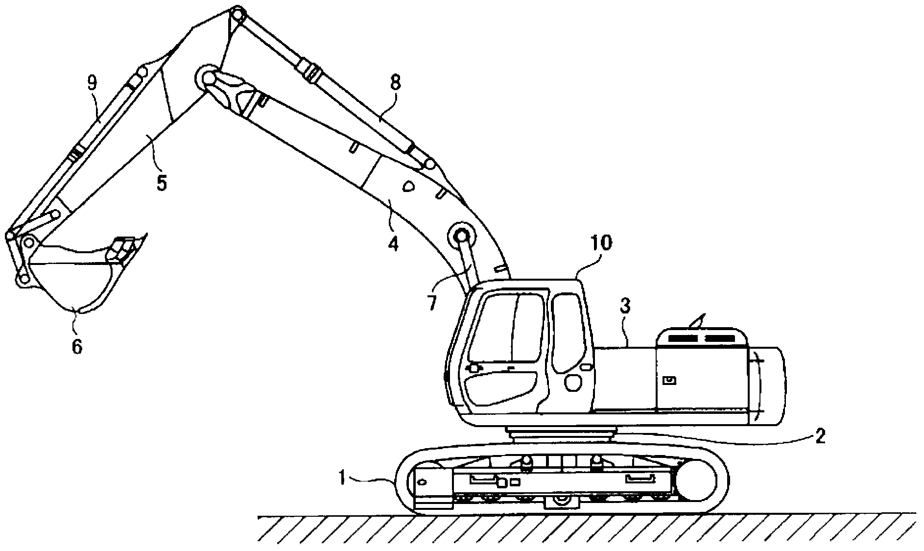
[0024] figure 1 It is a side view showing the hydraulic shovel according to the first embodiment of the present invention. In the hydraulic shovel, an upper revolving body 3 is mounted on a crawler-type undercarriage 1 through a revolving mechanism 2 so as to be rotatable.

[0025] The upper slewing body 3 is equipped with an excavation attachment including a boom 4 , an arm 5 , and a bucket 6 , and a boom cylinder 7 , an arm cylinder 8 , and a bucket cylinder 9 for driving them, respectively, at the front central portion. In addition, the upper revolving structure 3 is equipped with a cab 10 in which an operator rides in the front part, and is equipped with an engine (not shown) as a driving source in the rear part. Hereinafter, the boom cylinder 7 , the arm cylinder 8 , the bucket cylinder 9 , the traveling hydraulic motor (not shown), the swing hydraulic motor (not shown), and the like are collectively referred to as “hydraulic actuators”.

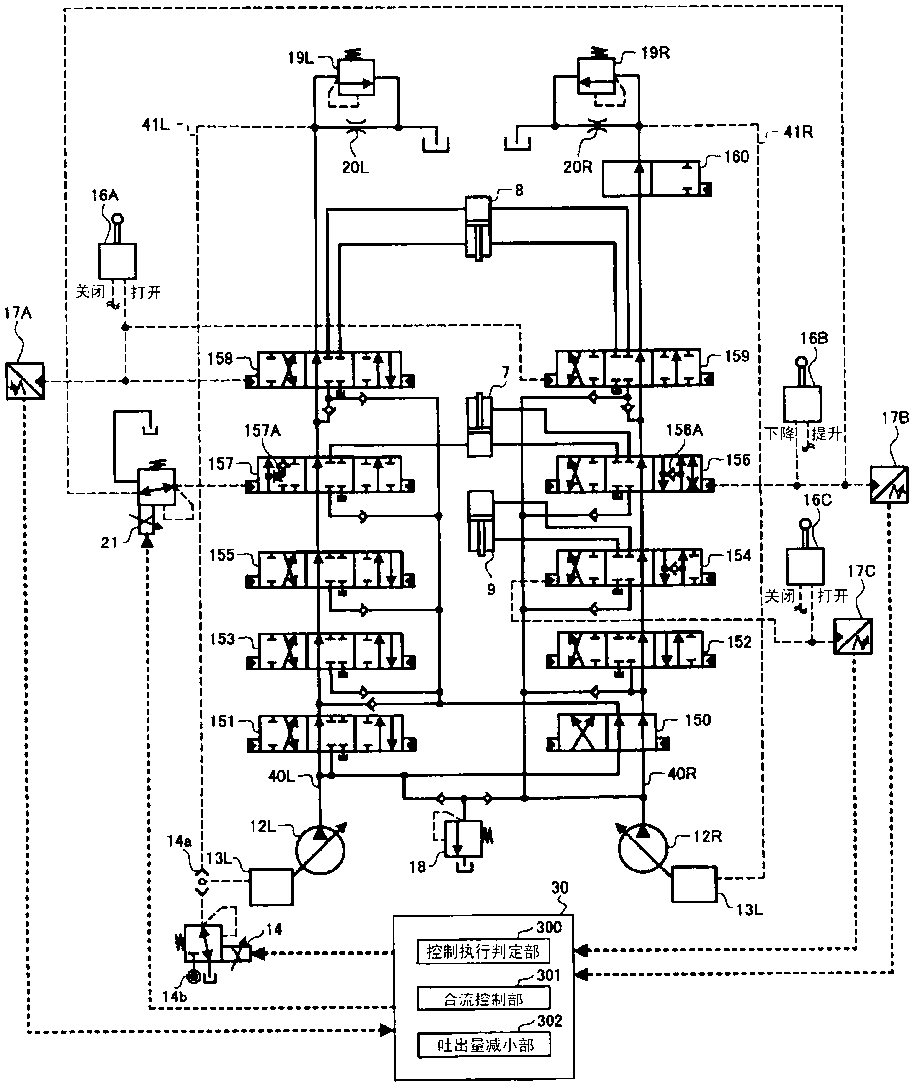
[0026] figure 2 It is a sche...

Embodiment 2

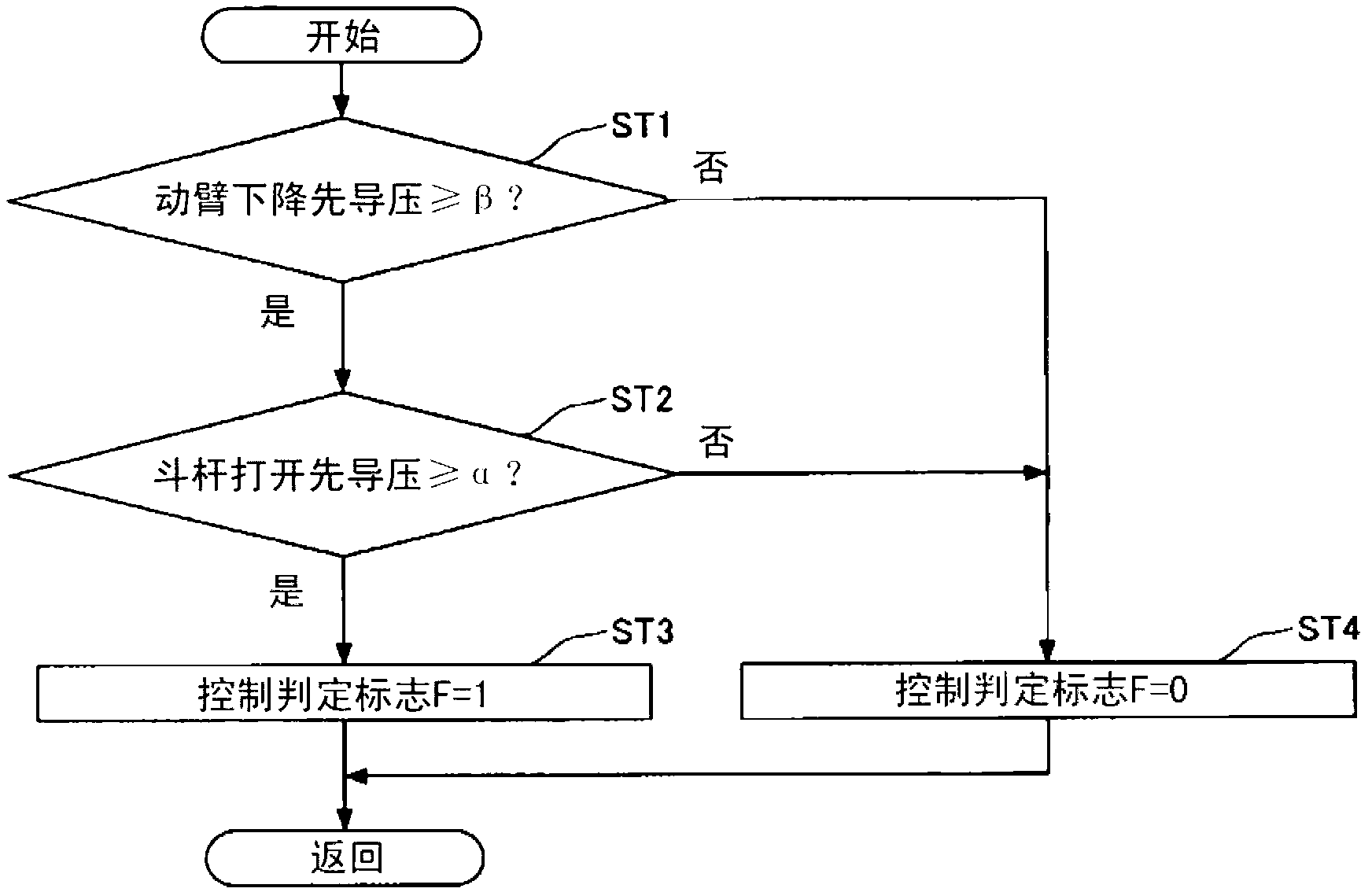
[0110] Next, refer to Figure 5 The control execution determination process executed in the hydraulic shovel according to the second embodiment of the present invention will be described. in addition, Figure 5 It is a flowchart showing the flow of control execution determination processing executed in the hydraulic shovel according to the second embodiment, and the control execution determination processing is continuously executed while the hydraulic shovel is in operation.

[0111] in addition, Figure 5 The control execution judgment processing of the control execution is different from the control start condition and the control release condition in that image 3 The control execution judgment processing is different.

[0112] Therefore, the description of the common points will be omitted, and the differences will be described in detail. In addition, the same reference signs as those used to describe the hydraulic shovel according to the first embodiment are used.

...

Embodiment 3

[0126] Next, refer to Image 6 and Figure 7 A hydraulic shovel according to a third embodiment of the present invention will be described. in addition, Image 6 It is a schematic diagram showing a configuration example of a hydraulic circuit mounted on a hydraulic shovel according to the third embodiment. Image 6 and figure 2 In the same way, the high pressure oil circuit, pilot oil circuit and electric drive / control system are represented by solid line, dotted line and dotted line respectively. in addition, Figure 7 It is a flowchart showing the flow of control execution determination processing executed in the hydraulic shovel according to the third embodiment, and the control execution determination processing is continuously executed while the hydraulic shovel is in operation.

[0127] Image 6 In the point of having the arm rod pressure sensor 17D and the arm cylinder bottom pressure sensor 17E, it is the same as the figure 2 The hydraulic circuits involved in...


PUM


Abstract

The invention provides a piece of construction machinery, comprising an oil hydraulic circuit which drives a bucket rod by pressure oil flows out from an oil chamber on a cylinder bottom of a boom cylinder. The construction machinery comprises a control device (30) which is provided with a control executing determining portion (300), a confluence control portion (301), and an output capacity reduction portion (302). The control executing determining portion (300) determines whether control start conditions are satisfied. The confluence control portion (301) controls inflow of the pressure oil which flows out from the oil chamber on the cylinder bottom of the boom cylinder to a stick cylinder (8). The output capacity reduction portion (302) controls output capacity of a main pump (12L). When the control device determines movable arm operation amount on a descent direction is in a scheduled intermediate operating area and bucket rod operation amount on an opening direction is in a scheduled upper limit side operating area through the control executing determining portion, the pressure oil which flows out from the oil chamber on the cylinder bottom of the boom cylinder flows in an oil chamber on a side a rod of the stick cylinder through the confluence control portion. Output capacity of the main pump is limited by the output capacity reduction portion.

Description

technical field [0001] The present invention relates to a construction machine provided with a hydraulic circuit that effectively utilizes pressure oil flowing out of a bottom-side oil chamber of a boom cylinder when the boom is operated in a downward direction. Background technique [0002] Conventionally, there is known a boom lowering regeneration circuit that supplies pressurized oil flowing out of the bottom side oil chamber of the boom cylinder to the rod side oil chamber of the boom cylinder when the boom is operated in the lowering direction (for example, refer to Patent Document 1 ). [0003] Patent Document 1: Japanese Patent Application Laid-Open No. 10-89317 [0004] However, since the rod penetrates the oil chamber, the volume of the rod-side oil chamber of the boom cylinder is smaller than that of the bottom-side oil chamber of the boom cylinder, so the total amount of pressurized oil flowing out of the bottom-side oil chamber cannot be recycled, Since the re...

Claims


Application Information

Patent Timeline
IPC IPC(8): E02F3/43E02F9/22
Inventor 桥本浩文
Owner SUMITOMO CONSTRUCTION MACHINERY
Why Eureka
Try Eureka