
Maximum entropy method used for traffic subnetwork trip matrix estimation

A technology of traffic network and traffic sub-network, which is applied in the field of travel matrix estimation of traffic sub-network, which can solve the problems of not considering network balance and difficulty in obtaining travel matrix information, etc.

Active Publication Date: 2018-05-01
SHANGHAI JIAO TONG UNIV
View PDF2 Cites 10 Cited by
  • Summary
  • Abstract
  • Description
  • Claims
  • Application Information

AI Technical Summary

Problems solved by technology

[0006] In the current method, when using the maximum entropy method to estimate the network travel matrix, the traffic is distributed according to the known ratio, without considering the balance of the network. On the other hand, when the network balance is considered, the current method uses the maximum entropy method to estimate the subnetwork In the travel matrix method, all or part of the travel matrix information is required in addition to the traffic observations, but it is often difficult to obtain the travel matrix information, and the traffic flow of the road network is easier to obtain, so the present invention proposes a method based only on Estimation method of sub-network travel matrix of traffic observations in each road segment

Method used


Image

  • Maximum entropy method used for traffic subnetwork trip matrix estimation
  • Maximum entropy method used for traffic subnetwork trip matrix estimation
  • Maximum entropy method used for traffic subnetwork trip matrix estimation

Examples


Embodiment Construction

[0084] The following is a detailed description of the embodiments of the present invention. This embodiment is carried out based on the technical solution of the present invention, and provides detailed implementation methods and specific operation processes.

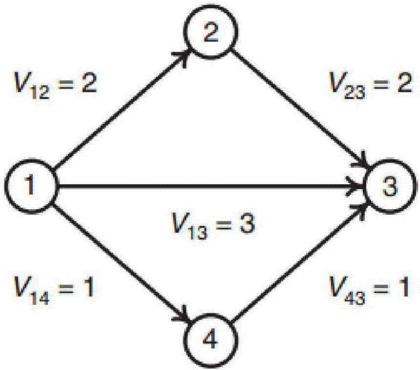
[0085] figure 1 Network calculation example:

[0086] Use below figure 1 Network example to illustrate the concrete algorithm steps of the model of the present invention:

[0087] S1: Extracting the network structure and parameters in the road traffic network

[0088] Abstract the traffic network in reality, and determine the network structure and model data parameters through data investigation and processing. The road network diagram of this example is attached figure 1 , in this network, N=R=S={1,2,3,4}, A={l 12 , l 13 , l 14 , l 23 , l 43} The row pairs are: (1,2), (1,3), (1,4), (2,3) and (4,3).

[0089] S2: Establish the maximum entropy model for solving the travel matrix of the sub-network:

[0090] ...


PUM


Abstract

The present invention relates to the field of traffic, especially to a maximum entropy method used for traffic subnetwork trip matrix estimation. The method comprises the following steps of: S1: selecting and establishing an abstracted sub traffic network, wherein the network is formed by a node set N and a road section set A, and the N comprises a starting point set R and a terminal point set S;S2: establishing and solving the maximum entropy model of a traffic subnetwork trip matrix; S3, in the abstracted sub traffic network, employing the maximum entropy model, performing initialization toobtain a feasible solution of the maximum entropy model, designing an algorithm to find and solve a current solution decreasing direction of decreasing of a target function value of the maximum entropy model; S4: performing linear search, performing solution, determining an optimal [Alpha], and determining the optimal step of the decreasing; S5: updating the feasible solution; and S6, allowing the algorithm to end the examination. The maximum entropy method used for the traffic subnetwork trip matrix estimation takes easily obtained flow of each road section of the whole network as unique input of the model to establish the maximum entropy problem so as to improve the algorithm efficiency, allow the method to be utilized in a large network and improve the prediction precision. The maximumentropy method used for the traffic subnetwork trip matrix estimation can be used for assessment of influences of different network changes on the subnetwork flow.

Description

technical field [0001] The invention relates to the field of traffic, in particular to a maximum entropy method for estimating the travel matrix of a traffic sub-network. Background technique [0002] With the improvement of people's living standards, the number of motor vehicles in each region continues to rise, and the transportation network tends to become larger and more complex. In order to improve the service level of the traffic road network, it is sometimes necessary to build new road sections or upgrade some existing road sections of the road network. Therefore, a tool is needed to measure the impact of road network changes on the traffic road network. [0003] When it is necessary to measure the flow change and impact of network changes on large-scale traffic networks such as urban road networks and cross-regional traffic road networks, due to the complexity of the network and the limitation of calculation time and cost, in actual traffic analysis, we often use sim...

Claims


Application Information

Patent Timeline
Patent Type & Authority Applications(China)
IPC IPC(8): G08G1/01
CPCG08G1/0125G08G1/0137
Inventor 谢驰苗雨刘海洋
Owner SHANGHAI JIAO TONG UNIV
Learn More