

Fan two-stroke engine
A two-stroke, engine technology, applied in the direction of machines/engines, combustion engines, internal combustion piston engines, etc., can solve the problems of high cost, high failure rate, complex system, etc., and achieve the effect of reducing production cost and energy consumption
- Summary
- Abstract
- Description
- Claims
- Application Information
AI Technical Summary
Problems solved by technology
Method used
Image

Examples
Embodiment 1
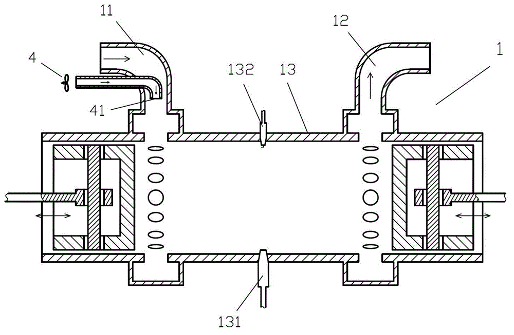
[0040] like figure 1 The fan two-stroke engine shown includes an opposed-piston two-stroke engine 1 and an electric fan 4, the air outlet 41 of the electric fan 4 is arranged in the air inlet 11 of the opposed-piston two-stroke engine 1, the The gas ejection direction of the air outlet 41 is the same as the gas flow direction in the air inlet 11, that is, the angle α between the gas ejection direction of the air outlet 41 and the gas flow direction in the air inlet 11 is equal to 0° .
[0041] When the engine starts to start, although the pressure of the gas ejected from the air outlet 41 is not too high, it can still effectively press fresh air into the cylinder of the opposed-piston two-stroke engine 1 from the air inlet 11. Inside the sleeve 13, a scavenging effect is generated to make the opposed-piston two-stroke engine 1 burn and do work, so as to achieve the purpose of starting.
[0042] The fuel nozzle 131 and spark plug 132 provided on the cylinder liner 13 of the ...
Embodiment 2
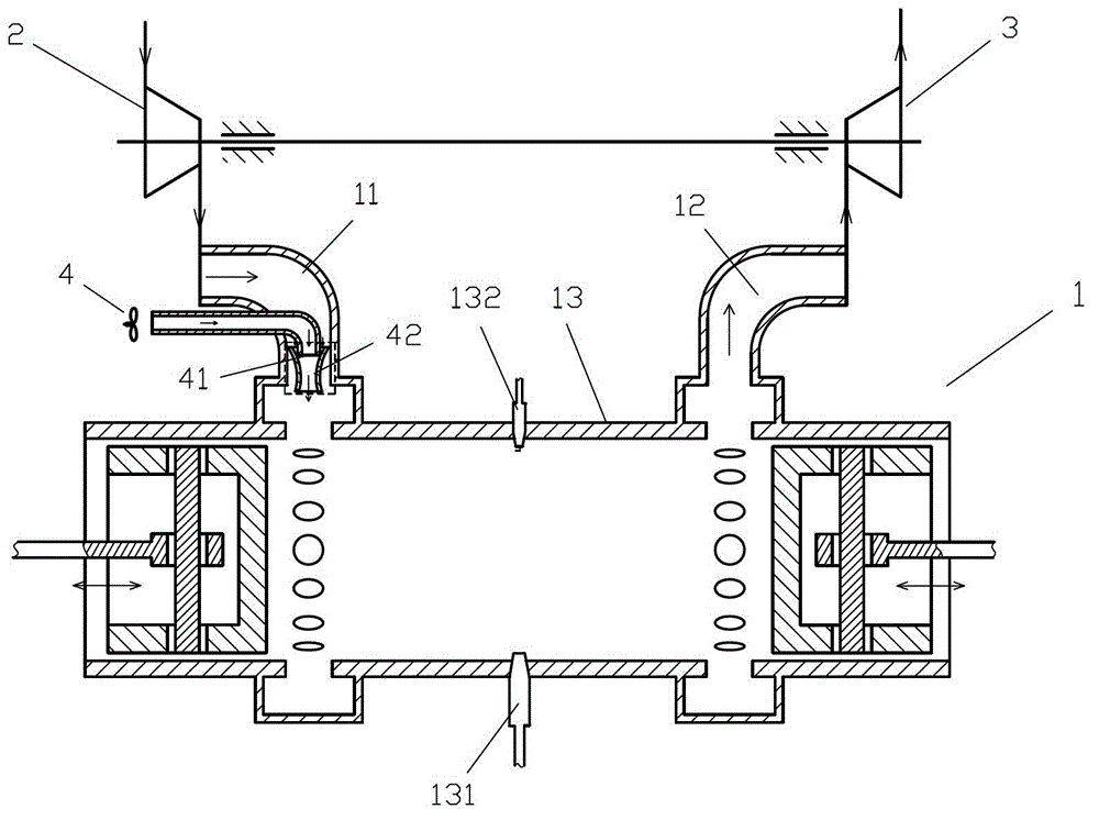
[0045] like figure 2 The difference between the fan two-stroke engine shown and Embodiment 1 is that a jet pump 42 is communicated at the air outlet 41, and the air outlet 41 is connected to the power gas injection port of the jet pump 42. The direction of the gas outlet of the jet pump 42 is the same as the direction of gas flow in the inlet passage 11, that is, the angle β between the direction of the gas outlet of the jet pump 42 and the direction of gas flow in the inlet passage 11 is equal to 0° Correspondingly, the airflow in the air intake passage 11 passes through the low-pressure gas inlet of the jet pump 42, and the airflow sent by the electric fan 4 passes through the gas outlet of the jet pump 42 and enters the cylinder liner 13.
[0046] Connect the intake duct 11 with the impeller compressor 2 on the traditional opposed-piston two-stroke engine 1, and the exhaust duct 12 of the opposed-piston two-stroke engine 1 communicate with the traditional opposed-piston t...
Embodiment 3
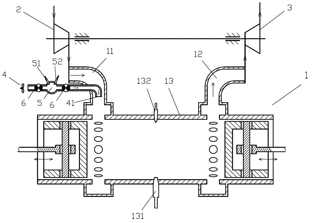
[0049] like image 3 The difference between the fan two-stroke engine shown and Embodiment 1 is that an external combustion chamber 5 and two check valves 6 are arranged on the pipeline between the main body of the electric fan 4 and the air outlet 41, A fuel inlet 51 and a spark plug 52 are provided on the external combustion chamber 5 , and the two check valves 6 are respectively provided on the channels on both sides of the external combustion chamber 5 .
[0050] In addition, in this embodiment, the inlet passage 11 communicates with the impeller compressor 2 , and the exhaust passage 12 communicates with the power turbine 3 . As an alternative embodiment, the power turbine 3 may output power to the outside instead of the impeller compressor 2, or the impeller compressor 2 and the power turbine 3 may not be provided or one of them may be provided.
PUM
 Abstract
Description
Claims
Application Information