

Structure of buffering type swing valve oil cylinder of concrete pump
A pendulum valve oil cylinder and concrete pump technology, which is applied to parts of pumping devices for elastic fluids, pump elements, variable capacity pump parts, etc., and can solve problems such as reduced equipment system life, loud equipment noise, and damaged equipment , to achieve the effect of overcoming the impact phenomenon
Inactive Publication Date: 2013-03-20
徐州宇家化工科技有限公司
View PDF0 Cites 0 Cited by
- Summary
- Abstract
- Description
- Claims
- Application Information
AI Technical Summary
Problems solved by technology
[0003] As we all know: the pendulum valve performs gap and high-frequency cycle action during the working process. The hydraulic cylinder or hydraulic system as the drive bears a large hydraulic shock during the working process. This hydraulic shock will not only cause a large noise in the equipment, What is more serious is that it is easy to reduce the life of the equipment system and damage the equipment. There is no good solution for this at present
Method used
View moreImage
Smart ImageViewing Examples

Examples
Embodiment Construction
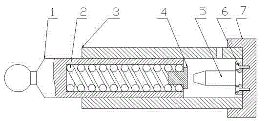
[0009] A structure of a concrete pump buffer pendulum valve cylinder, including a plunger 1, a compression spring 2, a cylinder body 3, an impact block 4, an impact rod 5, a bolt 6, and a cylinder head 7, and a plunger 1 is arranged in the cylinder body 3 A cylinder head 7 is arranged at the bottom of the cylinder body 3, a blind hole is formed in the middle of the plunger 1, a compression spring 2 is arranged in the blind hole in the middle of the plunger 1, and an impact block is fixedly installed on the outer end of the compression spring 2 4. Install and fix a striking rod 5 at the middle part of the cylinder head 4 through a bolt 6 .
Login to View More PUM
 Abstract
The invention provides a structure of a swing valve driving oil cylinder of a concrete pump. A plunger is arranged in a cylinder body; a cylinder cover is arranged at the bottom of the cylinder body; a compression spring is arranged in a blind hole formed in the middle of the plunger; a collision block is fixedly mounted at the outer end of the spring; and a collision rod is mounted and fixed in the middle in the cylinder cover through a bolt. According to the invention, impact phenomenon and damages due to the impact phenomenon in the working of the traditional swing valve driving oil cylinder of the concrete pump can be overcome.
Description
technical field [0001] The invention relates to a concrete pump, in particular to the structure of a concrete pump buffer pendulum valve oil cylinder, and belongs to the technical field of concrete pumps. Background technique [0002] The pendulum valve of the concrete pump is driven by the plunger cylinders arranged symmetrically on both sides of the pendulum valve, and the two driving cylinders do similar "push-pull" actions during the working process. [0003] As we all know: the pendulum valve performs gap and high-frequency cycle action during the working process. The hydraulic cylinder or hydraulic system as the drive bears a large hydraulic shock during the working process. This hydraulic shock will not only cause a large noise in the equipment, What is more serious is that it is easy to reduce the life of the equipment system and damage the equipment. To this, there is no good solution at present. Contents of the invention [0004] The purpose of the present ...
Claims
Login to View More Application Information
Patent Timeline
 Patent Type & AuthorityApplications(China)
IPC IPC(8): F04B53/10
Inventor王香善
Owner徐州宇家化工科技有限公司