Electronic proportioning valve and control system

A proportional control valve and control system technology, applied in the field of proportional valves, can solve the problems of low control precision, high equipment cost, many components, etc., and achieve the effects of high control precision, simple structure, flexible and simple operation

Pending Publication Date: 2022-03-08
广东鑫太自动化设备有限公司
View PDF7 Cites 0 Cited by
  • Summary
  • Abstract
  • Description
  • Claims
  • Application Information

AI Technical Summary

Problems solved by technology

[0003] Aiming at the defects of many and complex components, low control precision and high equipment cost in the above-mentioned prior art, the present invention provides an electronic proportional regulating valve to overcome the defects

Method used


Image

  • Electronic proportioning valve and control system
  • Electronic proportioning valve and control system
  • Electronic proportioning valve and control system

Examples


Embodiment 1

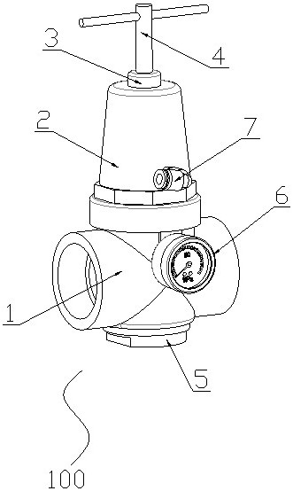
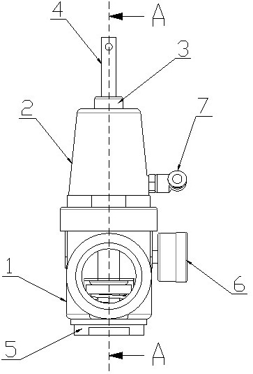
[0029] like figure 1 As shown, the first embodiment provides an electronic proportional regulating valve, which includes a proportional valve body 100 ; the proportional valve body 100 includes a valve body 1 and a conical upper cover 2 .

[0030] In this embodiment, specifically, an air inlet chamber 11 and an air outlet chamber 12 that communicate with each other are formed inside the valve body 1; The valve core assembly of high degree; the bottom of the valve body 1 is embedded with a bottom cover 5; the valve core assembly is elastically mounted on the bottom cover 5; the top of the valve body 1 is formed with a piston cavity 13; A piston 14 is slidingly installed in the piston cavity 13; one end of the spool assembly extends into the piston cavity 13 and is connected with the piston 14 in conflict; the upper cover 2 is provided with a preset valve for adjusting the preset threshold of the piston 14. pressure device; the side end of the upper cover 2 is provided with an ...

Embodiment 2

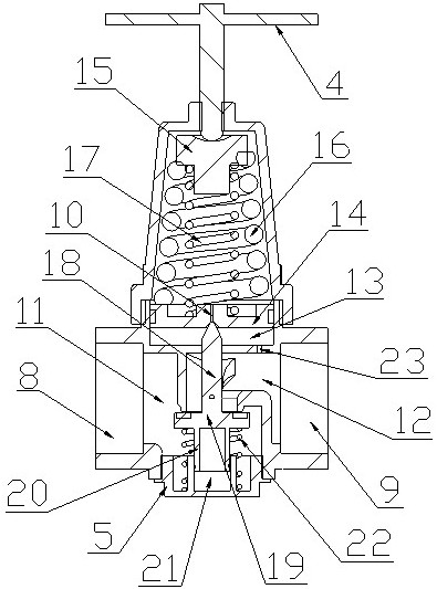
[0033] like Figure 1-3 As shown, this embodiment 2 contains all the technical features of embodiment 1, the difference is that: the valve core assembly includes a top post 18, a blocking plug 19 and a limit cylinder 20 from top to bottom; the top post 18 is far away from One end of the blocking plug 19 is a pointed structure; the pointed structure passes through the side wall of the valve body 1 and extends into the piston chamber 13; the pointed structure is in conflicting connection with the piston 14; the blocking plug 19 is used to open or close the intake air The connecting channel between the cavity 11 and the air outlet cavity 12; the inside of the bottom cover 5 has a limiting cavity 21; the limiting cylinder 20 is slidably installed in the limiting cavity 21; the bottom cover 5 and the blocking plug 19 There is a retaining spring 22 between them; when the spool assembly moves upward, the blocking plug 19 gradually reduces the opening of the electronic proportional re...

Embodiment 3

[0038] refer to Figure 4 , this embodiment 3 provides a control system, the system includes all the technical features of the above-mentioned embodiment 1 and embodiment 2, the difference is: the system also includes a distribution gas tank 200, a main switch valve 300 and a tee joint 400; The first port of the three-way joint 400 is connected to the main switch valve 300; the second port of the three-way joint 400 is connected to the air inlet 8 of the valve body 1; the air outlet 9 of the valve body 1 is connected to the distribution The gas tank 200 is connected; the main switch valve 300 is connected to the gas source; the distribution gas tank 200 is provided with several electromagnetic valve groups 900 for supplying gas to the gas unit; the outer wall of the distribution gas tank 200 is provided with a pressure Transmitter 500; the control system also includes a PLC control unit 600, a PID controller 700 and an electrical proportional control valve 800; the pressure tr...


PUM


Abstract

The invention discloses an electronic proportioning valve. The electronic proportioning valve comprises a proportioning valve body, the proportional valve body comprises a valve body and a conical upper cover; an air inlet cavity and an air outlet cavity which are communicated with each other are formed in the valve body; a valve element assembly used for controlling the opening degree of the valve body is arranged between the air inlet cavity and the air outlet cavity. A bottom cover is connected to the bottom of the valve body in an embedded mode. The valve element assembly is elastically installed on the bottom cover. A piston cavity is formed in the top of the valve body; a piston is arranged in the piston cavity in a sliding manner; one end of the valve element assembly extends into the piston cavity and is connected with the piston in an abutting mode. A pre-pressing device used for adjusting the preset threshold value of the piston is arranged in the upper cover. The side end of the upper cover is provided with an air valve with an air inlet or air outlet function; the outer side wall of the valve body is provided with a barometer used for detecting the pressure of gas in the gas outlet cavity. The electronic proportioning valve is simple in structure and high in control precision, stepless adjustment of pressure can be achieved, and the impact phenomenon during reversing of a switch type air valve is avoided.

Description

technical field [0001] The invention relates to the technical field of proportional valves, in particular to an electronic proportional regulating valve and a control system. Background technique [0002] The proportional valve includes a valve sleeve and a spool set in the valve sleeve. During the adjustment process, due to the current uncertain opening of the spool, it is necessary to adjust the spool to the zero point or the maximum threshold of the proportional valve. Then reopen the valve to a specific opening. At present, the electrical proportional valve completes the task through intermittent control, that is, switch control. In the pneumatic control system, switch-type reversing valves with low action frequency are used to control the on-off of the air circuit, the pressure reducing valve is used to adjust the required pressure, and the throttle valve is used to adjust the required flow rate. This traditional pneumatic control system not only requires many compone...

Claims


Application Information

Patent Timeline
Patent Type & Authority Applications(China)
IPC IPC(8): F15B13/02F15B19/00F15B21/08
CPCF15B13/02F15B19/00F15B21/08
Inventor 黄蒋才周剑
Owner 广东鑫太自动化设备有限公司
Why Eureka
Try Eureka