
Power distribution cabinet applied to high-humidity environment

A power distribution cabinet, high-humidity technology, applied in substation/power distribution device casing, static electricity, electrical components, etc., can solve problems such as shortened service life, inability to remove static electricity, collision between base and power distribution cabinet, etc., to ensure stable work , Improve the dehumidification effect and avoid the impact phenomenon

Inactive Publication Date: 2020-01-03
于洪海
View PDF8 Cites 0 Cited by
  • Summary
  • Abstract
  • Description
  • Claims
  • Application Information

AI Technical Summary

Problems solved by technology

[0003] In most parts of southern my country, there will be "plum rain" weather every year. This kind of weather will make the environment hot and humid. Hot and humid means high temperature and high humidity. In an environment with high humidity, if the long-term humidity in the power distribution cabinet is high, It will seriously affect the operation of electronic components in the outdoor electrical distribution cabinet and shorten its service life, so it is necessary to dehumidify the outdoor electrical distribution cabinet
During the use of the existing power distribution cabinet, static electricity will be generated on the power distribution cabinet, and the existing power distribution cabinet cannot remove the generated static electricity, which will affect the work of the staff and cause certain dangers
In addition, most of the bases of existing power distribution cabinets use simple shock-absorbing springs for shock absorption. Although they can meet their use requirements, the shock-absorbing effect is poor, and it is easy to cause collisions between the base and the power distribution cabinet during shock absorption. Phenomenon that affects the stability of the power distribution cabinet

Method used


Image

  • Power distribution cabinet applied to high-humidity environment
  • Power distribution cabinet applied to high-humidity environment
  • Power distribution cabinet applied to high-humidity environment

Examples


Embodiment 1

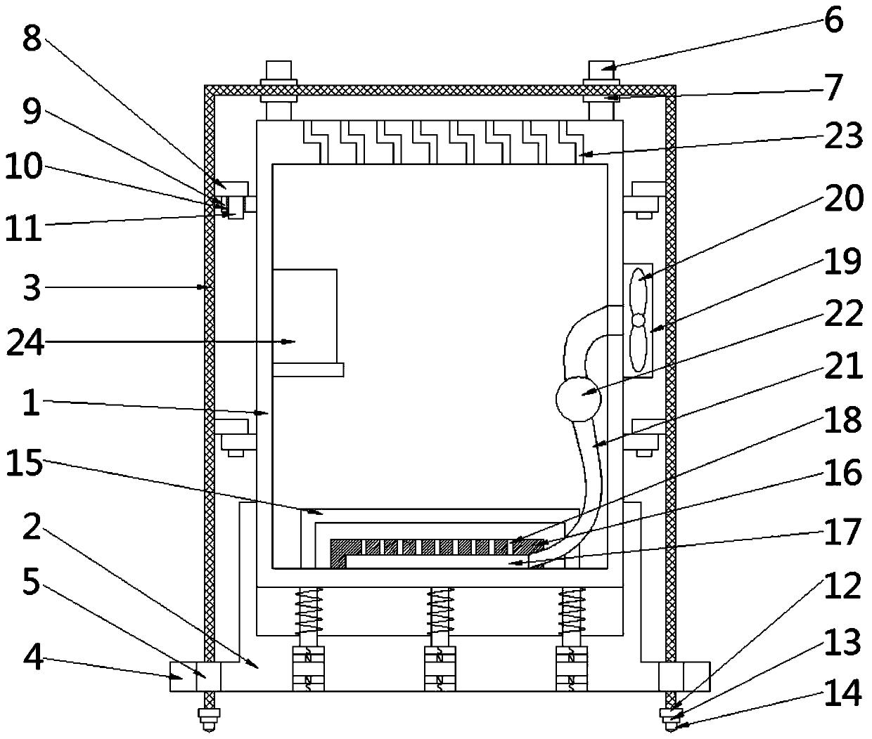
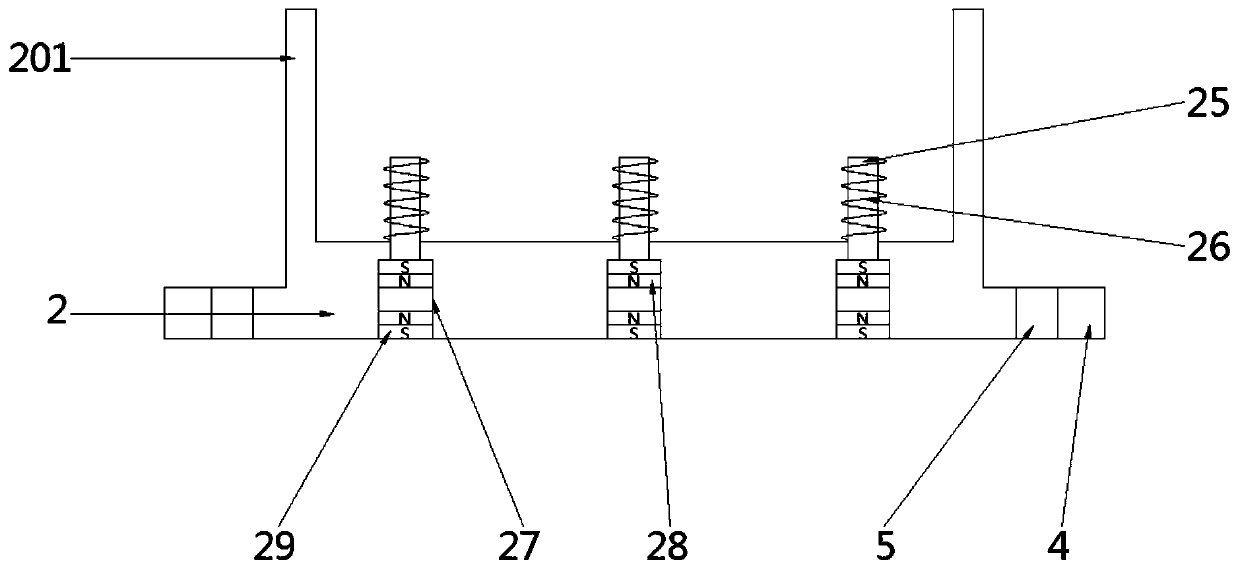
[0033] see Figure 1-3 , a power distribution cabinet used in a high-humidity environment, including a cabinet body 1, a base 2 arranged on the lower side of the cabinet body 1, and an anti-static net cover 3 outside the cabinet body 1. The left and right sides of the base 2 are integrally formed with Install the outer edge 4, the four corners of the installation outer edge 4 are provided with installation holes 5, the bottom four corners of the anti-static net cover 3 are connected with installation blocks 12, and each installation block 12 runs through the installation holes 5 corresponding to its position Setting, the bottom of each installation block 12 is connected with a grounding rod 13;

[0034] The anti-static net cover 3, the installation outer edge 4, the installation block 12, and the insertion rod 13 are all made of conductive materials.

[0035] The installation block 12 is a cylindrical structure, and the diameter of the installation block 12 is greater than th...


PUM


Abstract

The invention discloses a power distribution cabinet applied to a high-humidity environment, and belongs to the field of power equipment. The power distribution cabinet applied to a high-humidity environment comprises a cabinet body, a base arranged on the lower side of the cabinet body, and an anti-static mesh cover arranged on the outer side of the cabinet body. Installation outer edges are integrally formed on the left and right sides of the base. Installation holes are formed in the four corners of the installation outer edges. Installation clamping blocks are connected to the four cornersof the bottom of the anti-static mesh cover. The bottom of each installation clamping block is connected with a grounding insertion rod. A bearing net plate is arranged on the lower side in the cabinet body. A fixing plate is arranged at the bottom in the cabinet body. A cavity is formed in the fixed plate, and a plurality of ventilation openings are formed in the upper side of the fixing plate and are communicated with the cavity. A dust cover is arranged on the inner wall of the right side of the cabinet body. Continuous dehumidification of the interior of the cabinet body can be realized,and static electricity generated during working of the cabinet body can be eliminated to improve the safety. Moreover, the power distribution cabinet is convenient to install, position and use, and has good damping and buffering effects and high stability.

Description

technical field [0001] The invention relates to the field of electric equipment, and more specifically, relates to a power distribution cabinet applied in a high-humidity environment. Background technique [0002] The power distribution cabinet (box) is divided into power distribution cabinet (box), lighting distribution cabinet (box), metering cabinet (box), and is the final equipment of the power distribution system. The power distribution cabinet is a general term for the motor control center. The power distribution cabinet is used in the occasions where the load is relatively scattered and there are few circuits; the motor control center is used in the occasions where the load is concentrated and there are many circuits. They distribute the electric energy of a certain circuit of the upper-level power distribution equipment to the nearest load. This level of equipment shall provide protection, monitoring and control of the load. [0003] In most parts of southern my c...

Claims


Application Information

Patent Timeline
Patent Type & Authority Applications(China)
IPC IPC(8): H02B1/30H05F3/02H02B1/56H02B1/28H02B1/54
CPCH02B1/28H02B1/30H02B1/54H02B1/565H05F3/02
Inventor 不公告发明人
Owner 于洪海
Learn More