Thin film cutting device

A cutting and film technology, which is applied in the stacking receiving device, thin material handling, transportation and packaging, etc., can solve the problems of uneven film stacking, film burr production capacity, and unfavorable roll film cleaning, etc. It is convenient for subsequent process operations, high-quality cutting, and the effect of eliminating static electricity

Inactive Publication Date: 2017-05-31
GUANGDONG FXD INTELLIGENT EQUIP CO LTD
View PDF0 Cites 17 Cited by
  • Summary
  • Abstract
  • Description
  • Claims
  • Application Information

AI Technical Summary

Problems solved by technology

However, manual cutting has the disadvantages of low cutting accuracy, burrs on the membrane, and low production capacity. In addition, static electricity will be generated on the coiled film during the cutting process and contaminated with dust and other debris, which is not conducive to the cleaning of the coiled film. , and the presence of static electricity also leads to the defect that the diaphragms are not stacked neatly

Method used


Image

  • Thin film cutting device
  • Thin film cutting device
  • Thin film cutting device

Examples


Embodiment Construction

[0027] The present application will be described in further detail below in conjunction with the accompanying drawings and specific embodiments. It should be understood that the following exemplary embodiments and descriptions are only used to explain the present invention, not as a limitation to the present invention, and, in the case of no conflict, the embodiments in the application and the features in the embodiments can be combined with each other .

[0028] In order to explain the positional relationship of the structure more clearly, unless otherwise specified, the "downstream side" and "upstream side" mentioned below refer to the upstream side where the film passes first according to the traveling direction of the film, and the position where the film passes behind The position is on the downstream side.

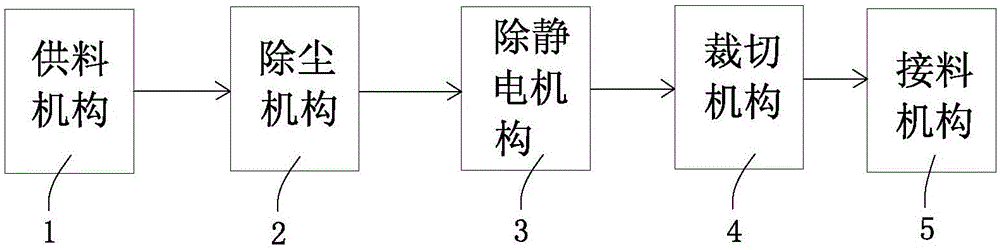
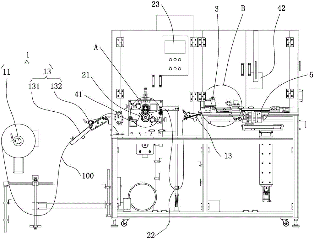
[0029] Such as Figure 1 to Figure 8 As shown, one embodiment of the present invention provides a film cutting device, comprising:

[0030] A feeding mechanism 1 ...


PUM


Abstract

The embodiment of the invention discloses a thin film cutting device. The thin film cutting device comprises a material supply mechanism, a dust removal mechanism, a cutting mechanism and an electrostatic eliminating mechanism; the cutting mechanism comprises a cutting base plate, a cutting pressing plate, a cutting knife and a driving piece; the cutting pressing plate is matched with the cutting base plate to clamp a thin film to be cut, and a cutting gap is formed in the cutting pressing plate; a cutting edge line intersects with the surface of the thin film to be cut to form a predetermined angle, and the knife point of the cutting knife penetrates through the cutting gap to cut the thin film; the driving piece drives the cutting knife to move reciprocally along the cutting gap to cut the thin film; the electrostatic eliminating mechanism comprises an electrostatic eliminating mechanism before cutting and an electrostatic eliminating mechanism after cutting. According to the embodiment of the invention, the cutting base plate and the cutting pressing plate are arranged, the cutting gap is formed in the cutting pressing plate for the cutting edge line to intersect with the surface of the thin film to be cut to form the predetermined angle, and the thin film is subjected to high-quality cutting; the surface cleanness of the cut film is effectively ensured and static electricity of the film is eliminated with the cooperation of the dust removal mechanism and the electrostatic eliminating mechanism; the thin film cutting device is beneficial to stacking films tidily.

Description

technical field [0001] Embodiments of the present invention relate to the technical field of film cutting, and in particular to a film cutting device. Background technique [0002] In industrial production, it is often necessary to cut the coiled film and other processing techniques. The existing cutting process usually uses manual cutting. The operator manually places the coiled film on the table, and then aligns it with a steel ruler. Manually cut the cutting line, and finally manually stack the cut membranes. However, manual cutting has the disadvantages of low cutting accuracy, burrs on the membrane, and low production capacity. In addition, static electricity will be generated on the coiled film during the cutting process and contaminated with dust and other debris, which is not conducive to the cleaning of the coiled film. , and the presence of static electricity also leads to the defect that the diaphragms are not stacked neatly. Contents of the invention [0003]...

Claims


Application Information

Patent Timeline
Patent Type & Authority Applications(China)
IPC IPC(8): B65H35/06B65H20/16B65H23/032B65H31/00B08B1/02B08B1/04B08B5/04H05F3/06
CPCB65H35/06B08B1/02B08B1/04B08B5/043B65H20/16B65H23/032B65H31/00B65H2301/44336B65H2301/5153B65H2701/1133B65H2701/1752H05F3/06
Inventor 侯立新
Owner GUANGDONG FXD INTELLIGENT EQUIP CO LTD
Why Eureka
Try Eureka