Attenuation force regulating type buffer

A damping force, adjustable technology, applied in the direction of shock absorber, shock absorber, liquid shock absorber, etc., can solve the problem of electromagnet enlargement, achieve the effect of large damping force and increase valve opening pressure

Active Publication Date: 2013-03-20
HITACHI LTD
View PDF7 Cites 10 Cited by
  • Summary
  • Abstract
  • Description
  • Claims
  • Application Information

AI Technical Summary

Problems solved by technology

Since the area of ​​the valve body of the pressure control valve is the pressure receiving area to adjust the internal pressure of the back pressure chamber, when the valve opening pressure is increased to increase the damping force on the hardware side, the solenoid will become larger

Method used


Image

  • Attenuation force regulating type buffer
  • Attenuation force regulating type buffer
  • Attenuation force regulating type buffer

Examples


Embodiment Construction

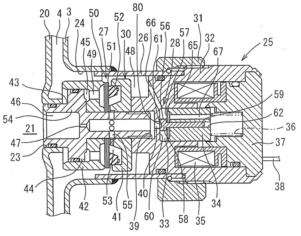
[0035] Hereinafter, reference techniques of the present invention will be described with reference to the drawings. Such as Figure 4 As shown, the damping force adjustable hydraulic shock absorber 1 (damping force adjustable shock absorber) of this technology is a double-layer cylinder structure with an outer cylinder 3 on the outside of the hydraulic cylinder 2, and between the hydraulic cylinder 2 and the outer cylinder 3 An oil storage chamber 4 is formed. A piston 5 is slidably embedded in the hydraulic cylinder 2, and the hydraulic cylinder 2 is divided into two chambers, a hydraulic cylinder upper chamber 2A and a hydraulic cylinder lower chamber 2B, by the piston 5 . One end of the piston rod 6 is connected with the piston 5 through the nut 7, and the other end side of the piston rod 6 passes through the upper chamber 2A of the hydraulic cylinder, passes through the guide rod 8 and the oil seal 9 installed on the upper end of the hydraulic cylinder 2 and the outer cyl...


PUM


Abstract

The invention relates to an attenuation force regulating type buffer which prevents operating lag of a pressure control valve and self-induced vibration of a valve body. The buffer controls oil flow between a cyclic oil channel (21) and an oil chamber (4) through a backpressure main valve 27 and the pressure control valve (28), and generates attenuation force. The oil flow between a cyclic oil channel (21) and an oil chamber (4) is generated by slide of a piston in a hydraulic cylinder. Direct attenuation force is generated through the pressure control valve (28), and internal pressure of a backpressure chamber (53) is adjusted to control open valve pressure of a main valve (27). The pressure control valve (28) is installed with a valve spring between a valve body (56) and a plunger (34), and mass of the valve body (56) is much lower than that of the plunger (34).Spring rigidity of the valve spring (57) is higher than that of the plunger spring (36). Thus, responsiveness of the valve body (56) is improved, and operating lag of attenuation force control is prevented. In addition, inherent frequency of the valve body (56) is improved, thereby preventing the self-induced vibration from occurring.

Description

[0001] The application date is March 27, 2009, the application number is 200910130681.2, the title of the invention is "damping force adjustable buffer", and the applicant is a divisional application of the Chinese invention patent application of Hitachi Manufacturing Co., Ltd. technical field [0002] The present invention relates to a damping force adjustable shock absorber mounted on a suspension device of a vehicle such as an automobile. Background technique [0003] The damping force adjustable shock absorber installed in the suspension device of the automobile is usually slidably embedded in the hydraulic cylinder sealed with oil, and the piston connected to the piston rod is slidably embedded, and the hydraulic cylinder is divided into two chambers. The damping force generating mechanism composed of a disc valve, etc. controls the flow of oil generated by the sliding of the piston in the hydraulic cylinder to generate damping force. The resistance changes, whereby the...

Claims


Application Information

Patent Timeline
Patent Type & Authority Applications(China)
IPC IPC(8): F16F9/46F16F9/19F16F9/34
Inventor 中楯孝雄根津隆片山洋平片山茂郎矢部博行
Owner HITACHI LTD
Why Eureka
Try Eureka