
Light source device

A light source device and light source technology, which are applied in projection devices, lighting devices, photolithography process exposure devices, etc., can solve the problem of inability to emit high-brightness light, and achieve the effect of improving utilization efficiency and high brightness

Inactive Publication Date: 2015-09-02
USHIO DENKI KK
View PDF6 Cites 0 Cited by
  • Summary
  • Abstract
  • Description
  • Claims
  • Application Information

AI Technical Summary

Problems solved by technology

[0008] However, it has been found that when the emitted light emitted from a plurality of LED light sources having different peak wavelengths is combined by a beam splitter, only the optical system of the above-mentioned structure is used to form a plurality of LED light sources and a beam splitter. It is only configured in a way, and cannot emit sufficient high-brightness light

Method used


Image

  • Light source device
  • Light source device
  • Light source device

Examples


Embodiment Construction

[0071] Hereinafter, embodiments of the present invention will be described in detail.

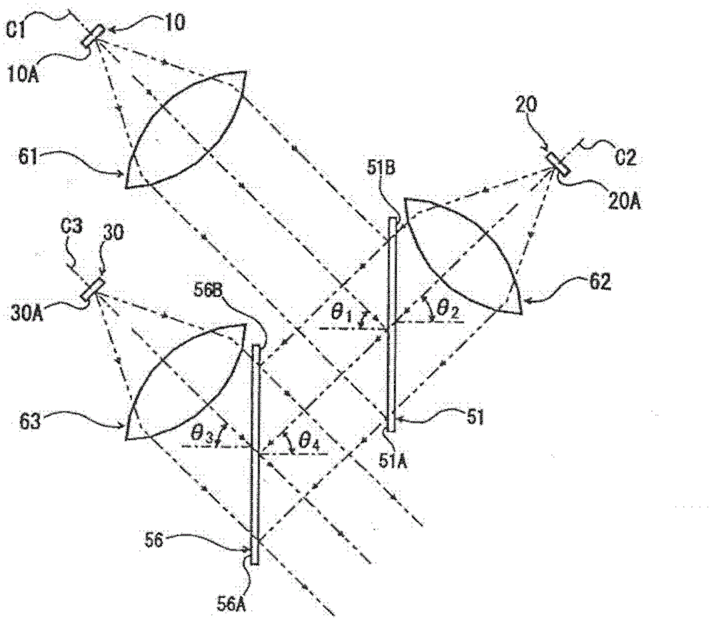
[0072] figure 1 It is an explanatory diagram showing a schematic structure of an example of the optical system of the light source device of the present invention.

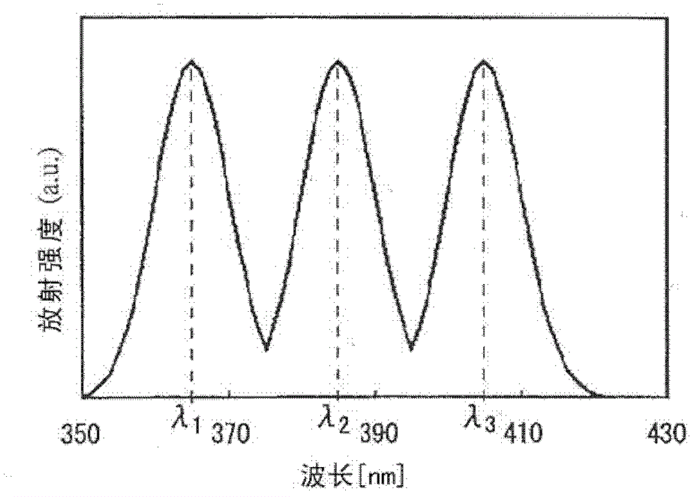
[0073] This optical system is to synthesize the respective radiations with mutually different peak wavelengths λ 1 [nm], λ 2 [nm] and λ 3 [nm](λ 1 >λ 2 >λ 3 ) optical system for emitting light from the first LED light source, the second LED light source, and the third LED light source of the three LED light sources.

[0074]In this optical system, the (circular) plate-shaped first beamsplitter 51 and the (circular) plate-shaped second beamsplitter 56 are displaced from one side to the other in the plane direction, and one side of the first beamsplitter 51 51A and the other surface 56B of the second dichroic mirror 56 are disposed opposite to each other, and the first LED element 10 constituting the first LED light sourc...


PUM


Abstract

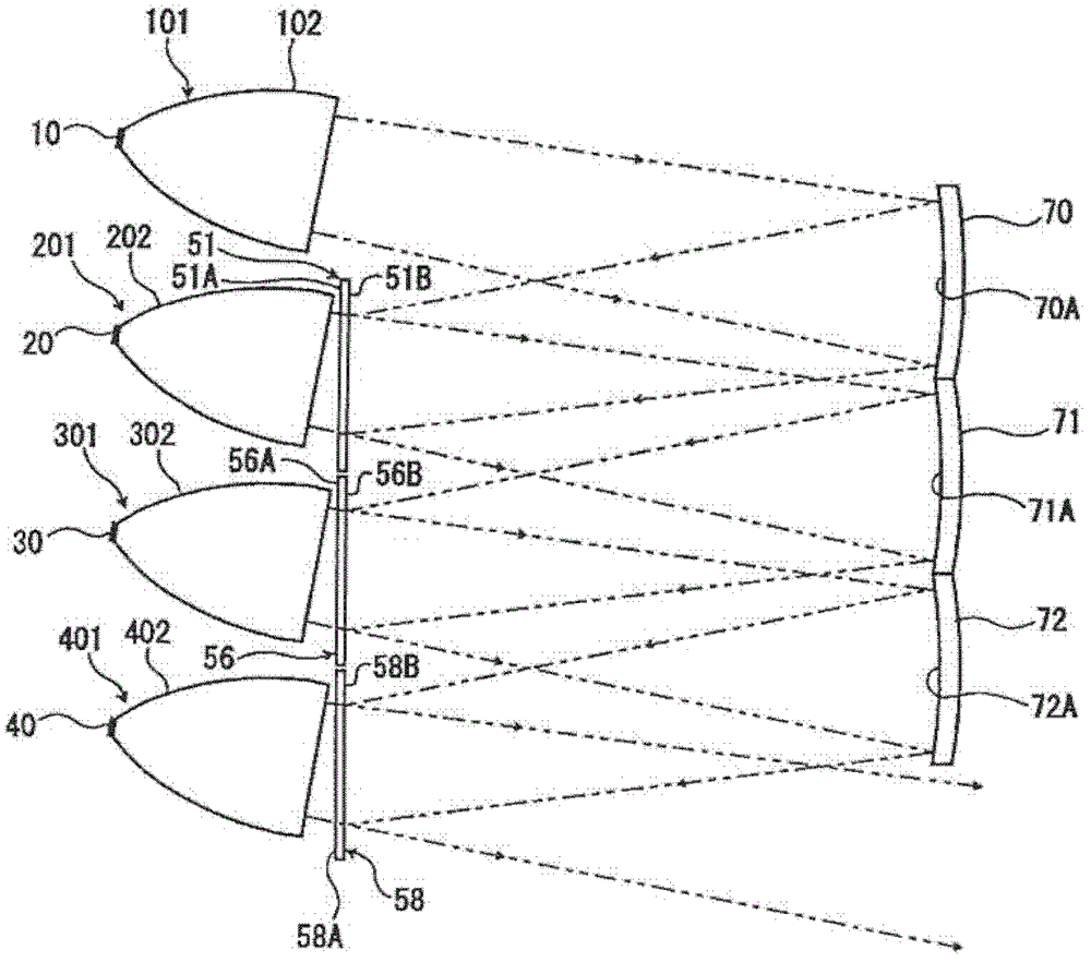
PROBLEM TO BE SOLVED: To provide a light source device which has a configuration to emit light by combining radiation light beams of multiple LED light sources and which emits light of a continuous wide wavelength range including a plurality of wavelength peaks and further provides a high luminance. SOLUTION: The light source device emits light by combining radiation light beams of three or more LED light sources having different peak wavelengths. The light source device includes a first dichroic mirror that combines a radiation light beam from a first LED light source with a radiation light beam from a second LED light source, and a second dichroic mirror that combines the combined light beam from the first dichroic mirror with a radiation light beam from a third LED light source. The second dichroic mirror reflects the combined light beam provided by the first dichroic mirror and transmits the radiation light beam from the third LED light source so as to obtain the combined light beam.

Description

technical field [0001] The present invention relates to a light source device used, for example, as a light source for exposure during exposure processing in manufacturing processes of semiconductors, liquid crystal substrates, color filters, etc., or as a light source of a projector device. Background technique [0002] For example, as an exposure light source used in the exposure process in the manufacturing process of semiconductors, liquid crystal substrates, color filters, etc., there are known Figure 4 The LED light emitting unit 80 formed by arranging a plurality of LED elements in the ultraviolet wavelength region in a planar manner condenses the radiated light emitted from the LED light emitting unit 80 through an appropriate condensing optical system. And emit to the light source device of the structure of exposure surface S (for example, refer patent document 1). exist Figure 4 Among them, symbol 81 is an elliptical reflector, 82 is a spherical lens, 83 is a con...

Claims


Application Information

Patent Timeline
Patent Type & Authority Patents(China)
IPC IPC(8): G02B27/10G03F7/20G03B21/20F21V9/40
CPCG03F7/2004G03F7/70008G03F7/70233G03F7/70391G03F9/7065
Inventor 松岛竹夫芜木清幸
Owner USHIO DENKI KK
Learn More