Driving voltage compensation system for GOA circuit

A driving voltage and compensation system technology, applied in instruments, static indicators, etc., can solve problems such as low current of thin film transistors, reduced electron mobility, and decreased charging capacity of thin film transistors, so as to achieve improved resolution and accurate driving voltage compensation Effect

Inactive Publication Date: 2013-03-20
AU OPTRONICS (XIAMEN) CORP +1
View PDF0 Cites 41 Cited by
  • Summary
  • Abstract
  • Description
  • Claims
  • Application Information

AI Technical Summary

Problems solved by technology

[0004] However, in the actual operation of the GOA circuit, low temperature conditions are often encountered, the electron mobility becomes smaller at low temperatures, and the current flowing through the thin film transistor is low, resulting in a decrease in the charging capacity of the thin film transistor.
In order to solve this problem, one solution in the prior art is to connect a temperature sensor such as a thermistor externally to the system, use the temperature sensor to detect the ambient temperature, and automatically increase the driving voltage of the GOA circuit when the ambient temperature is too low , to improve the charging capacity of thin film transistors, but this solution requires an external temperature sensing component, which not only increases the cost, but also occupies a volume
In addition, the temperature sensing component is exposed outside the panel and is easily affected by the external environment, resulting in a decrease in sensor sensitivity
Furthermore, the temperature sensing component detects the ambient temperature, which cannot accurately reflect the actual temperature of the TFT of the GOA circuit in the glass substrate.

Method used


Image

  • Driving voltage compensation system for GOA circuit
  • Driving voltage compensation system for GOA circuit
  • Driving voltage compensation system for GOA circuit

Examples


Embodiment Construction

[0020] In order to make the technical content disclosed in this application more detailed and complete, reference may be made to the drawings and the following various specific embodiments of the present invention, and the same symbols in the drawings represent the same or similar components. However, those skilled in the art should understand that the examples provided below are not intended to limit the scope of the present invention. In addition, the drawings are only for schematic illustration and are not drawn according to their original scale.

[0021] The specific implementation manners of various aspects of the present invention will be further described in detail below with reference to the accompanying drawings.

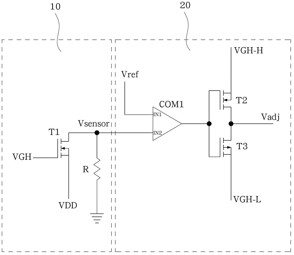
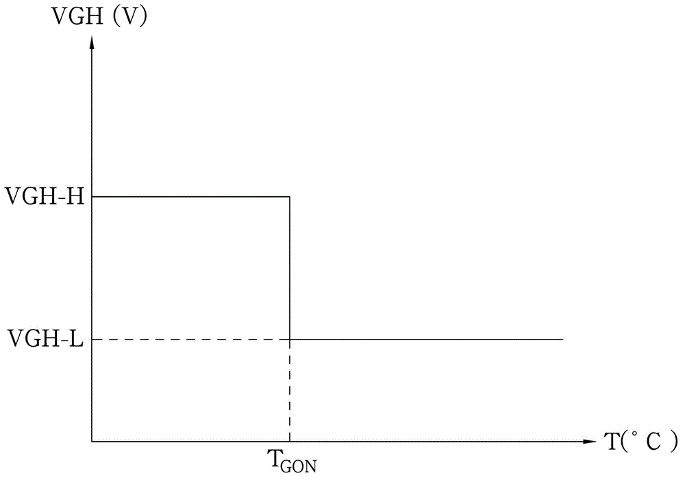
[0022] figure 1 A schematic structural diagram of a driving voltage compensation system for a GOA circuit is shown according to an embodiment of the present invention. figure 2 show figure 1 A graph showing the relationship between the first threshold v...


PUM


Abstract

The invention provides a driving voltage compensation system for a GOA (Gate driver On Array) circuit. The GOA circuit is positioned in an array substrate. The system comprises a temperature sensor and a driving circuit, wherein the temperature sensor is arranged below the GOA circuit and used for detecting real-time temperature of the array substrate and converting the real-time temperature to a voltage signal, and the driving circuit is used for receiving the voltage signal, comparing the voltage signal with reference voltage, outputting a control signal according to a compared result, and adjusting driving voltage of the GOA circuit by virtue of the control signal. Compared with the prior art, according to the driving voltage compensation system, the temperature sensor is placed in glass, so that the driving voltage compensation system is not affected by an external environment easily, can detect actual temperature actually reflecting a thin film transistor in the GOA circuit, and provides precise driving voltage compensation.

Description

technical field [0001] The present invention relates to a GOA (Gate driver On Array, array substrate row drive) circuit of a thin film transistor liquid crystal display (TFT-LCD, Thin Film Transistor Liquid Crystal Display), in particular to a driving voltage compensation system for the GOA circuit. Background technique [0002] Currently, in TFT-LCD, each pixel has a thin film transistor (TFT, Thin Film Transistor), the gate of the thin film transistor is electrically connected to the horizontal scanning line, and the drain is electrically connected to the vertical data line , and the source is electrically connected to a pixel electrode. If enough positive voltage is applied to a scanning line in the horizontal direction, all the TFTs on the scanning line will be turned on. At this time, the pixel electrode corresponding to the scanning line will be connected to the data line in the vertical direction, and the data line will be The video signal voltage is written into the...

Claims


Application Information

Patent Timeline
Patent Type & Authority Applications(China)
IPC IPC(8): G09G3/36
Inventor 彭少朋林佳丽
Owner AU OPTRONICS (XIAMEN) CORP
Why Eureka
Try Eureka