Barrel type upper and lower yoke structure three-phase isolation transformer

A technology of isolating transformers and yoke structures, applied in the field of transformers, which can solve problems such as complex structures, difficulty in adjusting transformer no-load current, troublesome assembly, etc.

Inactive Publication Date: 2015-08-26
DONGGUAN GUANGHUA IND
View PDF4 Cites 0 Cited by
  • Summary
  • Abstract
  • Description
  • Claims
  • Application Information

AI Technical Summary

Problems solved by technology

[0003] like Figure 7 As shown, it shows the structure of the iron core in a typical three-phase transformer in the traditional technology. The iron core of this structure is assembled by three horizontal pieces 2 and three iron core columns 1 in an interlaced manner. Its structure It is more complex and cumbersome to assemble, especially, it is difficult to adjust the no-load current of the transformer by adjusting the iron core

Method used


Image

  • Barrel type upper and lower yoke structure three-phase isolation transformer
  • Barrel type upper and lower yoke structure three-phase isolation transformer
  • Barrel type upper and lower yoke structure three-phase isolation transformer

Examples


Embodiment Construction

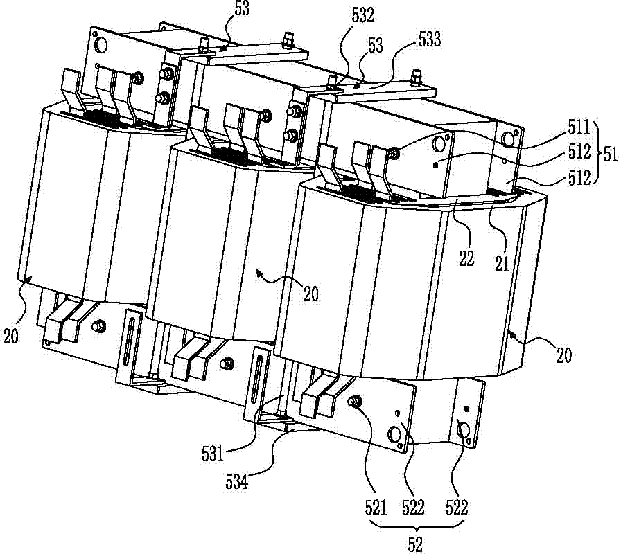
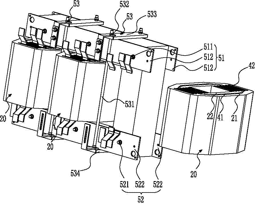
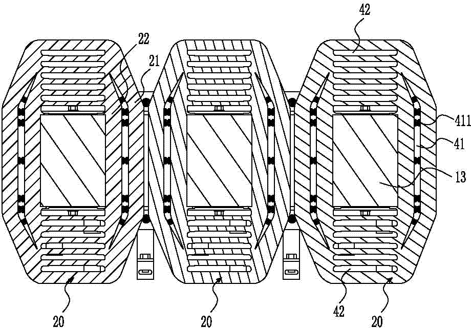
[0034] Please refer to Figure 1 to Figure 6 As shown, it shows the specific structure of the preferred embodiment of the present invention, including an iron core 10, a winding 20, and a fixing structure for fixing the winding 20 and the iron core 10. Each winding 20 includes a primary winding 21 and Secondary winding 22.

[0035] Such as Figure 4 to 6 As shown, the iron core 10 includes an upper yoke 11, a lower yoke 12, and three center pillars 13. The three center pillars 13 are arranged side by side in parallel, and the top and bottom edges are correspondingly flush. The yokes 12 are respectively located at the upper and lower positions of the center column 13, and an air gap 30 is formed between the upper yoke 11, the lower yoke 12 and the top and bottom ends of the center column 13, by adjusting the upper and lower yokes 11, 12 and The size of the air gap 30 between the center pillars 13 can be adjusted so that the no-load current can be adjusted.

[0036] Such as Figure ...


PUM


Abstract

The invention discloses a cylindrical three-phase isolation transformer with an upper and lower yoke structure, which comprises an iron core, windings and a fixing structure for fixing the windings and iron core. Each winding comprises a primary winding and a secondary winding. The iron core comprises an upper yoke, a lower yoke and three middle columns. The upper and the lower yokes respectively form air gaps with the top and the bottom ends of the middle columns. The primary and secondary windings are sequentially sleeved in the peripheries of corresponding middle columns from inside to outside. A full air flue located between the primary and secondary windings is arranged in the periphery of the primary winding. Conventional iron core is replaced by the upper and lower yoke structure, thus, the air gaps between the upper and lower yokes and the middle columns can be conveniently adjusted to adjust a no-load current. The full air flue is adopted between the primary and secondary windings to adjust the distance between the primary and secondary windings so as to adjust the short-circuit impedance. Meanwhile, the full air flue is designed so that the transformer has a better ventilating and radiating condition and low temperature rise, so that the service life of the transformer is prolonged, and the use cost is lowered.

Description

Technical field [0001] The invention relates to the field of transformer technology, in particular to a three-phase isolation transformer with a cylindrical upper and lower yoke structure. Background technique [0002] In electrical equipment and wireless circuits, transformers are often used to step up and down the voltage, and the transformer is a device that uses the principle of electromagnetic induction to change the AC voltage. A traditional three-phase transformer includes an iron core with three iron core legs and a plurality of cross-pieces, and windings sheathed on each iron core leg. The winding includes a primary winding and a secondary winding. [0003] Such as Figure 7 As shown, it shows the structure of the iron core in a three-phase transformer that is more representative in the traditional technology. The iron core of this structure is assembled by three horizontal sheets 2 and three iron core posts 1 in a staggered manner. It is more complicated and troublesome t...

Claims


Application Information

Patent Timeline
Patent Type & Authority Patents(China)
IPC IPC(8): H01F30/12H01F27/26H01F27/30
Inventor 陈锦棠方朝晖
Owner DONGGUAN GUANGHUA IND
Why Eureka
Try Eureka