Three phase earthing switch structure driven by duplex pull rods and distributed in I shape

A technology of grounding switch and double pull rod, which is applied in the direction of electric switch, high-voltage air circuit breaker, electrical components, etc. It can solve the problems of sudden drop of clamping force of the contact finger, burning of the grounding switch, and sudden increase of contact resistance, so as to reduce the closing Effects of resistance, reliable operation, reduced torsional deformation

Active Publication Date: 2013-03-20
CHINT ELECTRIC
View PDF7 Cites 2 Cited by
  • Summary
  • Abstract
  • Description
  • Claims
  • Application Information

AI Technical Summary

Problems solved by technology

[0002] Usually the three-phase grounding switches attached to the outdoor high-voltage AC isolation switch are arranged in parallel. When opening and closing, the three-phase grounding switches are carried out in three parallel planes. Each phase grounding switch consists of a static contact and It is composed of a moving contact. When the two contacts are in the closed position, the two rows of parallel fingers of the moving contact clamp the static contact. Yes, when the electrical contacts of the contacts heat up or the spring insulation is unfavorable for shunting, the spring will be overheated and annealed for permanent deformation, and the spring function will be lost, which will cause a sudden decrease in the clamping force of the fingers and a sudden increase in the contact resistance, causing the circuit to overheat and burn the grounding switch
And usually the installation position of the contact is fixed and cannot be adjusted, and the contact will not be used if it is slightly deformed by external force during field operation

Method used


Image

  • Three phase earthing switch structure driven by duplex pull rods and distributed in I shape
  • Three phase earthing switch structure driven by duplex pull rods and distributed in I shape
  • Three phase earthing switch structure driven by duplex pull rods and distributed in I shape

Examples


Embodiment Construction

[0018] In order to make the present invention more comprehensible, preferred embodiments are described in detail below with accompanying drawings.

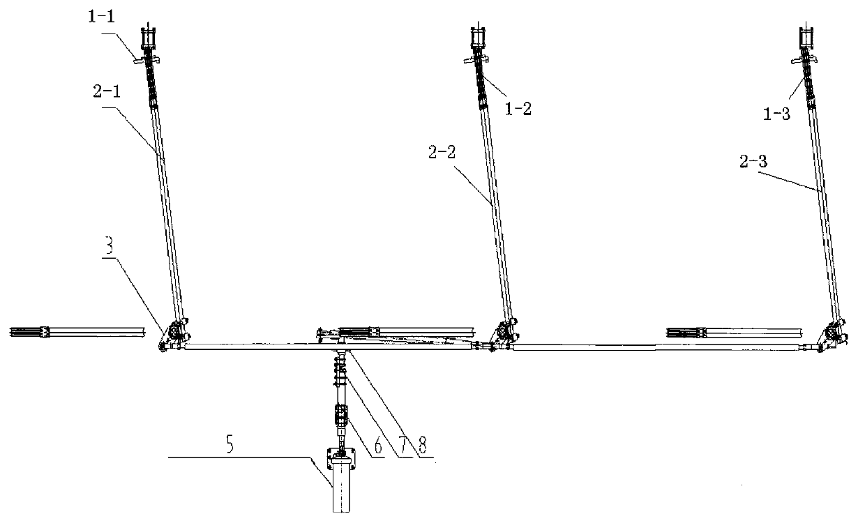
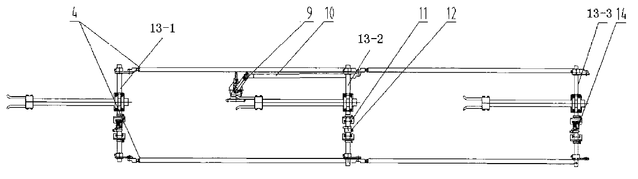
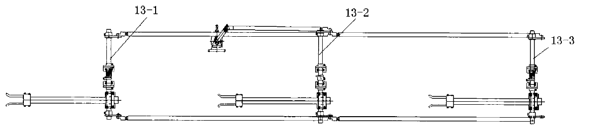
[0019] Such as figure 1 and figure 2 As shown, the present invention provides a three-phase inline arrangement grounding switch structure driven by double tie rods, including A phase moving contact assembly 2-1, B phase moving contact assembly 2-2 and C Phase A moving contact assembly 2-3, one end of A phase moving contact assembly 2-1, B phase moving contact assembly 2-2 and C phase moving contact assembly 2-3 are respectively connected to A phase static contact assembly 1- 1. Phase B static contact assembly 1-2 and C phase static contact assembly 1-3, the other ends of which are respectively tightly hugged with A phase rotating shaft 13-1, B phase rotating shaft 13-2 and C phase rotating shaft 13-3, A-phase rotating shaft 13-1, B-phase rotating shaft 13-2 and C-phase rotating shaft 13-3 respectively pass through A-phase bent ...


PUM


Abstract

The invention relates to a three phase earthing switch structure driven by duplex pull rods and distributed in an I shape. The structure is characterized in that the structure comprises an A phase moving contact component, a B phase moving contact component and a C phase moving contact component which are distributed in the I shape, one ends of the A phase moving contact component, the B phase moving contact component and the C phase moving contact component are connected with an A phase static contact component, a B phase static contact component and a C phase static contact component respectively, and the other ends of the A phase moving contact component, the B phase moving contact component and the C phase moving contact component are tightly embraced with an A phase rotating shaft, a B phase rotating shaft and a C phase rotating shaft respectively. The three phase earthing switch structure driven by the duplex pull rods and distributed in the I shape has the advantages that a main conducting element has self-compression capability, the structure is simple, the performances are reliable, the entire earthing switch is in a detachable structure, convenient to install, flexible and wide in application, the adjustment is facilitated, and the through-current capability of the switch can be adjusted by increasing or reducing the number of contact fingers of the moving contacts.

Description

technical field [0001] The invention relates to a new type of three-phase grounding knife attached to an outdoor AC high-voltage isolation switch, which acts synchronously in the same plane when opening and closing, arranged in a straight line, the grounding knife is driven by double pull rods, and the installation position can be adjusted The self-pressing grounding switch structure of the present invention is the key structure of an outdoor high-voltage AC isolating switch in a high-voltage power transmission and transformation system, and belongs to the technical field of high-voltage switches. Background technique [0002] Usually the three-phase grounding switches attached to the outdoor high-voltage AC isolation switch are arranged in parallel. When opening and closing, the three-phase grounding switches are carried out in three parallel planes. Each phase grounding switch consists of a static contact and It is composed of a moving contact. When the two contacts are in...

Claims


Application Information

Patent Timeline
Patent Type & Authority Applications(China)
IPC IPC(8): H01H31/00
Inventor 韩际昌张永善叶彩霞林晨亮唐小江刘全都
Owner CHINT ELECTRIC
Why Eureka
Try Eureka