Wireless Real-time Monitoring System of Nitrogen Pressure in Transit for Large Transformers

A real-time monitoring and transformer technology, applied in the transmission system, wireless communication, signal transmission system, etc., can solve the problems of excessive pressure value, failure to alarm in time, and pressure value cannot be observed and stored in time, so as to avoid the expansion of faults, The effect of simple external structure and convenient installation and use

Active Publication Date: 2015-08-26
STATE GRID CORP OF CHINA +1
View PDF3 Cites 0 Cited by
  • Summary
  • Abstract
  • Description
  • Claims
  • Application Information

AI Technical Summary

Problems solved by technology

[0003] In order to ensure that the nitrogen pressure in the transformer maintains a stable range during transportation, it is often necessary to manually observe and record the display value of the pressure gauge to adjust the nitrogen pressure; the traditional inflation pressure gauge has a relatively single function, which is used to measure the pressure value of the equipment inflated and The generation of readings cannot meet the requirements of real-time acquisition of monitoring data, and there are many disadvantages, such as:
[0004] 1. The nitrogen pressure value in the transformer cannot be saved in real time during transportation;
[0005] 2. The sudden pressure value cannot be observed and saved in time;
[0006] 3. The pressure value is too large or too small to report to the police in time;
[0007] 4. Failure of the monitoring device itself cannot be detected in time;
[0008] The above-mentioned problems lead to the fact that the data observed during the transportation cannot really guarantee the quality of the transformer transportation, which brings inconvenience to the transportation of large transformers

Method used


Image

  • Wireless Real-time Monitoring System of Nitrogen Pressure in Transit for Large Transformers
  • Wireless Real-time Monitoring System of Nitrogen Pressure in Transit for Large Transformers

Examples


Embodiment Construction

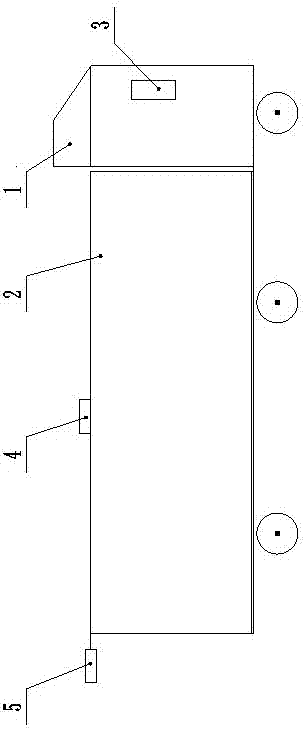
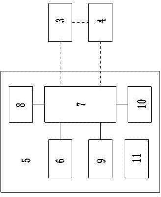
[0025] Such as figure 1 As shown, the wireless real-time monitoring system for nitrogen pressure of a large transformer in transit of the present invention includes a centralized controller 3 installed in the driver's cab of the large transformer transport vehicle 1, a router 4 installed on the top of the large transformer 2 and installed on the tail of the large transformer transport vehicle 1 The wireless real-time monitoring device 5 for nitrogen pressure at the top, the above-mentioned centralized controller 3, the router 4 and the wireless real-time monitoring device 5 for nitrogen pressure can communicate through a wireless network.

[0026] The above-mentioned centralized controller 3 sends commands to the router 4 and the nitrogen pressure wireless real-time monitoring device 5, and stores the information sent by the router 4 and the nitrogen pressure wireless real-time monitoring device 5; the router 4 mainly plays the role of auxiliary information transmission, and th...


PUM


Abstract

The invention relates to a wireless real-time monitoring system of an in-transit nitrogen pressure in a large transformer, which belongs to the technical field of conveyance monitor of the large transformer and solves the technical problem of providing a device capable of accurately and wirelessly monitoring the in-transit nitrogen pressure in the large transformer for a long time. The system is characterized by comprising an integrated controller installed at the cab of the transport vehicle of the large transformer, a router installed at the top end of the large transformer and a wireless real-time monitoring device of nitrogen pressure installed at the upper part of the tail of the transport vehicle of the large transformer, wherein the integrated controller, the router and the wireless real-time monitoring device of nitrogen pressure are all in wireless network communication; the integrated controller stores information sent by the router and the wireless real-time monitoring device of nitrogen pressure; and the wireless real-time monitoring device of nitrogen pressure comprises a nitrogen pressure sensor for collecting nitrogen pressure. The wireless real-time monitoring system is suitable for the field of the transportation of large transformers.

Description

technical field [0001] The invention relates to a wireless real-time monitoring system for nitrogen pressure of a large transformer in transit, belonging to the technical field of large transformer transportation monitoring. Background technique [0002] With the acceleration of smart grid construction, the demand for large-scale transformers is gradually increasing in various places. If the large-scale transformers of 110KV and above are transported with oil, the weight will increase, which will easily cause equipment damage or potential safety hazards. Nitrogen is filled in the tank so that the body does not come into contact with the air and avoid damp and rust; since the air pressure in the transformer oil tank is required to be kept at 0.01-0.03MPa to prevent mechanical deformation caused by external air leakage and overpressure, it needs to be transported in nitrogen. The pressure is monitored during the process; the traditional nitrogen air pressure monitoring device ...

Claims


Application Information

Patent Timeline
Patent Type & Authority Patents(China)
IPC IPC(8): H04L29/08H04W84/18G08C17/02
Inventor 杨北革任远高明张晓鹏段小兵郭小龙梁利生张金梅梁俊媛
Owner STATE GRID CORP OF CHINA
Why Eureka
Try Eureka