
Compound type monomer multi-effect steam mechanical recompression evaporator

A steam machinery and composite technology, which is applied to multi-effect evaporation, vertical tube evaporator, etc., can solve the problems of large space occupation, low speed and efficiency, large steam volume, etc., and achieves small space occupation, simple structure and economical efficiency. energy effect

Active Publication Date: 2013-03-27
贵港市飞创节能设备有限公司
View PDF5 Cites 17 Cited by
  • Summary
  • Abstract
  • Description
  • Claims
  • Application Information

AI Technical Summary

Problems solved by technology

However, in the process of evaporating and concentrating materials, the steam for heating, evaporating and concentrating materials is only used once, and the single-effect energy consumption is relatively high.
Theoretically, the multi-effect evaporator can use primary steam in several processes, so it is more energy-saving; the fly in the ointment is that the speed and efficiency are relatively low, and the existing multi-effects are used in series with several streams. The system is large in size and takes up a lot of space, so the heat dissipation is large due to the large volume, and the thermal loss is also large
For example, a set of three-effect evaporator steams a ton of water with only 33% theoretical steam, but the actual steam used is far greater than the theoretical value.

Method used


Image

  • Compound type monomer multi-effect steam mechanical recompression evaporator
  • Compound type monomer multi-effect steam mechanical recompression evaporator
  • Compound type monomer multi-effect steam mechanical recompression evaporator

Examples


Embodiment Construction

[0017] Below in conjunction with accompanying drawing, the present invention will be further described.

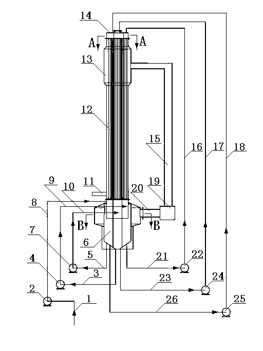
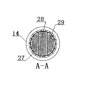
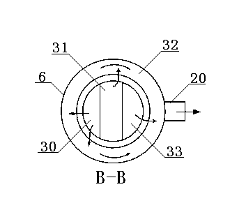
[0018] figure 1 Shown is the structural representation of the present invention. As can be seen from the figure, taking a composite single-unit multi-effect steam-mechanical recompression evaporator with a single-unit three-effect structure as an example, it is mainly composed of a distributor 14, a heater 13 and a steam-water separation chamber 6 that are sequentially connected and connected from top to bottom. The fixed connection constitutes an integral body, and there are three feed pumps 2, 4, 7 and circulation pumps 22, 24, 25 respectively. The steam mechanical compression pump 19 communicates the steam-water separation chamber 6 with the heater 13 through the steam output pipe 20 and the steam pipe 15. The material input end of the steam-water separation chamber 6 is connected with the feed pipe 1 through the first-level feed pump 2 and the first-level feed pipe 8,...


PUM


Abstract

The invention discloses a compound type monomer multi-effect steam mechanical recompression evaporator. The compound type monomer multi-effect steam mechanical recompression evaporator comprises a material distributing device, a heater, a steam-water separation chamber and a steam mechanical compression pump, and is characterized in that the material distributing device, the heater and the steam-water separation chamber are sequentially communicated from top to bottom and fixedly connected into a whole; the steam mechanical compression pump can communicate and connect the steam-water separation chamber with the heater through a pipeline; and a material input end of the steam-water separation chamber is connected with a feed pump through the pipeline, and a material output end is communicated and connected with the material distributing device through the pipeline and a circulating pump. The evaporator has the advantages of simple structure and small occupied space, and can achieve the effects of single-effect efficiency, multi-effect evaporation and energy conservation. Secondary steam produced by evaporation of material is recompressed by the steam mechanical pump and then used for heating the material, so that the circulating use is realized and the energy is saved. After the evaporator is opened and runs normally, the fresh steam does not need to be supplemented. The evaporator is suitable for evaporation and concentration of various liquid-containing materials.

Description

technical field [0001] The invention relates to an evaporation concentration equipment, especially a single-effect and multi-effect vapor mechanical compression evaporator. technical background [0002] Among the existing evaporators used for evaporation and concentration of materials, single-effect and multi-effect evaporators are used more. In use, it is found that the single-effect evaporator has a relatively high efficiency of material evaporation and concentration due to the direct vacuuming of the vacuum device. However, in the process of evaporating and concentrating materials, the steam for heating and evaporating and concentrating materials is only used once, and the single-effect energy consumption is relatively high. Theoretically, the multi-effect evaporator can use primary steam in several processes, so it is more energy-saving; the fly in the ointment is that the speed and efficiency are relatively low, and the existing multi-effects are used in series wi...

Claims


Application Information

Patent Timeline
IPC IPC(8): B01D1/12B01D1/26
Inventor 李锦龙
Owner 贵港市飞创节能设备有限公司
Learn More