

Welding device
A welding device and welding voltage technology, applied in welding equipment, arc welding equipment, manufacturing tools, etc., can solve problems such as difficult to manage input heat or weld bead shape, achieve stable droplet growth, high welding stability, and prevent deformation get unstable effect
- Summary
- Abstract
- Description
- Claims
- Application Information
AI Technical Summary
Problems solved by technology
Method used
Image

Examples
Embodiment approach 1
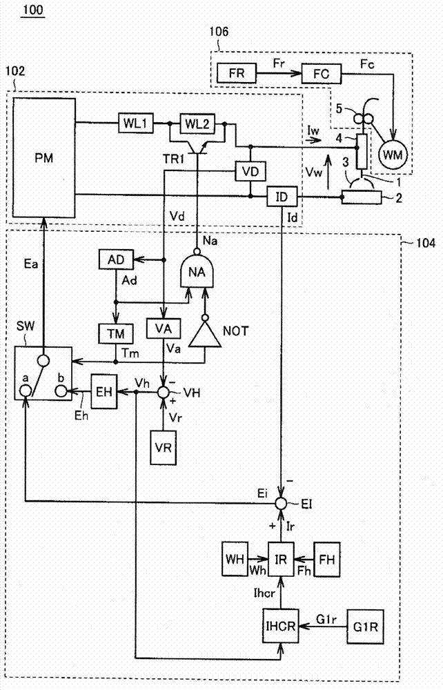
[0038] figure 1 It is a block diagram of the welding apparatus of Embodiment 1.
[0039] refer to figure 1 , the welding device 100 includes a power circuit 102 , a power control device 104 , a welding wire feeding device 106 , and a welding torch 4 .
[0040] The power control device 104 controls the power circuit 102 so that the welding current Iw and the welding voltage Vw output to the welding torch 4 become values suitable for welding.
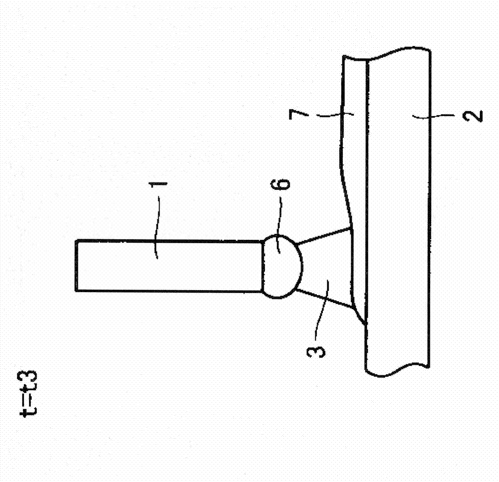
[0041] The welding wire feeding device 106 feeds the welding wire 1 to the welding torch 4 . Although not shown in the figure, shielding gas mainly composed of carbon dioxide is discharged from the tip portion of the welding torch 4 . An arc 3 is generated between the welding wire 1 protruding from the tip of the welding torch 4 and the base material 2 , and the welding wire 1 is melted to weld the base material 2 . The wire feeding device 106 includes a feeding speed setting circuit FR, a feeding control circuit FC, a feeding motor...
Embodiment approach 2
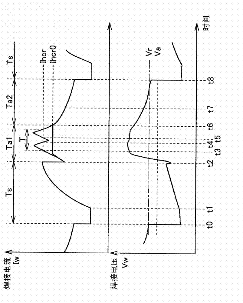
[0099] In Embodiment 1, the magnitude of the high-level current was changed based on the voltage difference between the set voltage Vr and the average voltage Va, but in Embodiment 2, the magnitude of the high-level current was changed based on the voltage difference between the set voltage Vr and the average voltage Va. figure 2 The period of the indicated high-level current (the first arc period Ta1).
[0100] Figure 7 It is a block diagram showing the structure of 100 A of welding apparatuses of Embodiment 2. In the following description, only the parts different from Embodiment 1 will be described, and the same parts as Embodiment 1 will be given the same reference numerals, and the description will not be repeated.
[0101] refer to Figure 7 , the welding device 100A includes a power circuit 102 , a power control device 104A, a welding wire feeding device 106 , and a welding torch 4 .
[0102] The power control device 104A is in figure 1 The configuration of the p...
Embodiment approach 3
[0111] In Embodiment 1, only the amplitude center current setting signal Ihcr is increased or decreased based on the voltage difference (Vr-Va), that is, the voltage error signal Vh. In Embodiment 2, only the first arc is increased or decreased based on the voltage difference. Period Ta1.
[0112] In Embodiment 3, upper and lower thresholds are set for the voltage difference, only the amplitude center current setting signal Ihcr is increased or decreased until the threshold, and only the first arc period Ta1 is increased or decreased for a voltage difference exceeding the threshold or a voltage difference smaller than the threshold.
[0113] Figure 8 It is a block diagram showing the structure of welding apparatus 100B of Embodiment 3. In the following description, only the parts different from Embodiment 1 will be described, and the same parts as Embodiment 1 will be given the same reference numerals, and the description will not be repeated.
[0114] refer to Figure 8, ...
PUM
 Abstract
Description
Claims
Application Information