Welding device

A welding device and arc technology, applied in welding equipment, arc welding equipment, manufacturing tools, etc., can solve the problems of overall deterioration of the weld edge of the weld bead, deterioration of welding quality, unstable droplet size, etc., and achieve high welding stability The effect of stability and stable droplet growth

Active Publication Date: 2013-01-09
DAIHEN CORP
View PDF8 Cites 0 Cited by
  • Summary
  • Abstract
  • Description
  • Claims
  • Application Information

AI Technical Summary

Problems solved by technology

However, in the case of welding with a high current (a current exceeding 200 A when the diameter of the welding wire is 1.2 mm) by the carbon dioxide gas arc welding method, in the droplet transfer accompanied by a short circuit, the droplet is caused by the reaction force of the arc. The bulge (せり上がゐ) is on the top of the welding wire, so the arc time is prolonged and it is difficult to produce periodic short circuits, and arcs and short circuits will occur irregularly
[0007] In this way, if the cycle of short circuit and arc fluctuates irregularly, the droplet size at the time of short circuit will become unstable, and the overall bead portion of the weld bead will deteriorate.
[0008] In addition, because the high current exerts excessive arc force at irregular positions relative to the weld pool, the weld pool becomes large and vibrates irregularly, especially by pushing the weld pool to the side opposite to the welding direction, then Prone to humping weld bead
[0009] In particular, the welding speed is required to be set at a high speed in order to increase productivity, but the deterioration of the welding quality due to the influence of the above-mentioned problems is remarkably manifested in high-speed welding

Method used


Image

  • Welding device
  • Welding device
  • Welding device

Examples


Embodiment approach 1

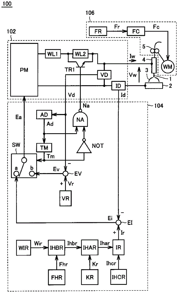
[0029] figure 1 It is a block diagram of the welding apparatus concerning Embodiment 1.

[0030] refer to figure 1 , The welding device 100 includes: a power circuit 102 , a power control device 104 , a welding wire feeding device 106 and a welding torch 4 .

[0031] The power supply control device 104 controls the power supply circuit 102 so that the welding current Iw and the welding voltage Vw output to the welding torch 4 become values ​​suitable for welding.

[0032] The welding wire feeding device 106 feeds the welding wire 1 to the welding torch 4 . Although not shown in the figure, a shielding gas mainly composed of carbon dioxide gas is released from the tip portion of the welding torch 4 . An arc 3 is generated between the welding wire 1 protruding from the tip of the welding torch 4 and the base material 2 , the welding wire 1 is melted, and the base material 2 is welded. The wire feeding device 106 includes a feeding speed setting circuit FR, a feeding contro...

Embodiment approach 2

[0089] In Embodiment 2, in addition to the welding method described in Embodiment 1, spatter can be reduced by detecting droplet constriction before arc generation and reducing current before arc generation.

[0090] Figure 8 It is a block diagram showing the structure of 100 A of welding apparatuses concerning Embodiment 2. In the following description, only the parts different from Embodiment 1 will be described, and the same parts as Embodiment 1 will be given the same reference numerals without repeating description.

[0091] refer to Figure 8 , The welding device 100A includes: a power circuit 102A, a power control device 104A, a welding wire feeding device 106 and a welding torch 4 .

[0092] power supply circuit 102A except figure 1 In addition to the configuration of the power supply circuit 102 shown, a transistor TR2 and a current reducing resistor R are included. Transistor TR2 is inserted in series with reactors WL1 and WL2 at the output of power supply main...


PUM


Abstract

The invention provides a carbon dioxide gas electric arc welding method and a welding device for reducing splashing and improving welding quality. The welding device comprises a power supply circuit for supplying voltage between a welding torch and a base material, and a power supply control device for controlling the voltage of the power supply circuit. The power supply control device controls the power supply circuit in a manner that a high level current superimposed with a wave form which increases and decreases with a specified period and has an gradually increasing amplitude is outputted in a first electric arc period Ta1 in the early stage of an electric arc period following a short circuit period Ts, and constant voltage control is performed in a second electric arc period Ta2 in the later stage of the electric arc period. Through the superimposing of the wave form with the amplitude increasing as a molten drop grows, the intumesce of the molten drop caused by counter-acting force of the electric arc is prevented, and the stable formation of the molten drop and the improvement of the growing speed of the molten drop are realized.

Description

technical field [0001] The invention relates to a welding device, in particular to a welding device for carbon dioxide gas arc welding. Background technique [0002] Japanese Patent Application Publication No. 4-4074 (Patent Document 1) discloses a consumable-electrode arc welding method in which short-circuiting and arc generation are repeated between a consumable electrode and a base material. The consumable electrode arc welding method repeats the formation process of the droplet and the transition process of the droplet to the base metal. [0003] Figure 10 It is a diagram for explaining a consumable-electrode arc welding method in which short-circuiting and arc generation are repeated. [0004] refer to Figure 10 , in the consumable-electrode arc welding method in which short-circuiting and arc generation are repeated, the processes (a) to (f) described below are repeatedly performed sequentially. (a) The initial state of short circuit when the droplet is in contact...

Claims


Application Information

Patent Timeline
Patent Type & Authority Applications(China)
IPC IPC(8): B23K9/095B23K9/16
Inventor 井手章博惠良哲生
Owner DAIHEN CORP
Why Eureka
Try Eureka