
Discharge device of vacuum drying device

A technology of vacuum drying equipment and discharge device, which is applied in the field of chemical raw material drying, and can solve the problems of poor material in and out, easy jamming of the gate, poor air tightness, etc.

Inactive Publication Date: 2013-03-27
戴克
View PDF3 Cites 2 Cited by
  • Summary
  • Abstract
  • Description
  • Claims
  • Application Information

AI Technical Summary

Problems solved by technology

However, due to the structure, sealing and other reasons, as well as the limited drying capacity, it cannot be applied to the drying of a large number of plastic raw materials.
[0003] For example, the invention patent with the application number of 200610153867.6 discloses a resin dryer with a gate mechanism, which adopts a one-way moving sliding closing plate as the gate of the inlet and outlet pipe in the discharge pipe, not only the airtightness is not good, but also the material entering and exiting It is easy to jam the gate and cause the material to enter and exit smoothly
[0004] In addition, the shape of plastic raw materials changes in a vacuum state. Due to volume expansion, there will be an aggregation effect. When the vacuum state is released, the aggregated raw materials will form a bridging phenomenon, which is not easy to be discharged naturally, and a continuous supply of plastic raw materials cannot be formed.
Since the drying of chemical raw materials is a continuous process, the dried raw materials need to be discharged from the drying cylinder immediately for molding production, so the poor entry and exit of materials during the vacuum drying process has seriously affected the production process and efficiency of the entire enterprise

Method used


Image

  • Discharge device of vacuum drying device
  • Discharge device of vacuum drying device
  • Discharge device of vacuum drying device

Examples


Embodiment Construction

[0020] The technical solutions of the present invention will be further described below in conjunction with the accompanying drawings and embodiments.

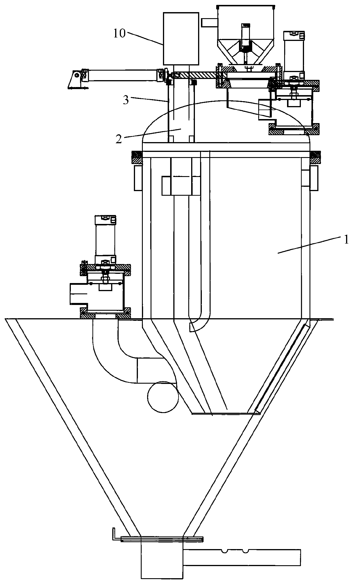
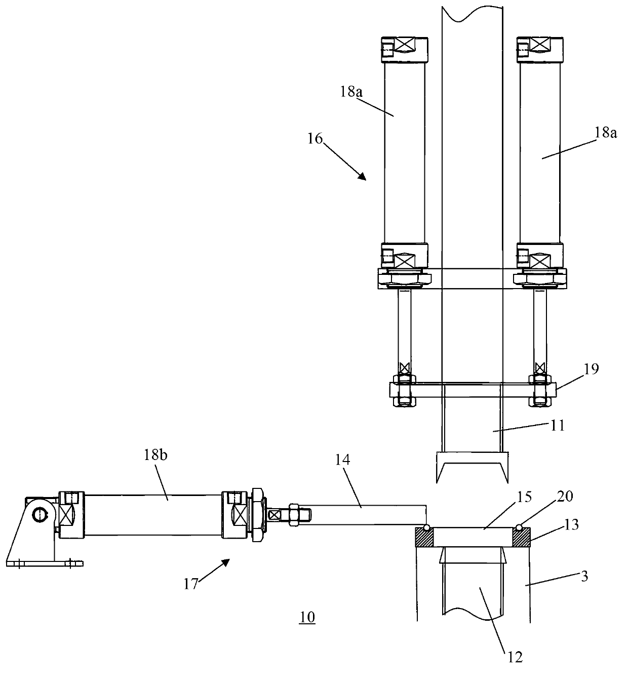
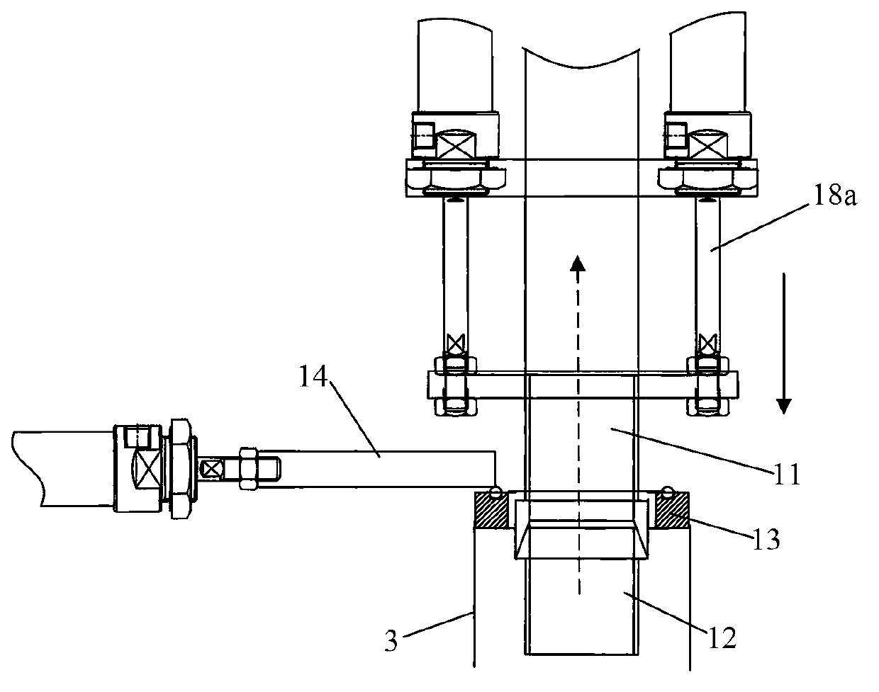
[0021] see Figure 1 to Figure 6 As shown, the discharge device 10 of the vacuum drying equipment of the present invention is connected to the discharge port 2 of the drying cylinder 1, including an outer casing 3, an upper discharge pipe 11, a lower discharge pipe 12, a valve seat 13 and a valve plate 14, The outer casing 3 is sleeved outside the lower discharge pipe 12, and its bottom and the bottom of the lower discharge pipe 12 are connected with the discharge port 2, and the upper discharge pipe 11 is arranged above the lower discharge pipe 12, and the valve The seat 13 has a valve hole 15 and is fixed on the upper end of the outer casing 3, the height of which is higher than the upper end of the lower discharge pipe 12, and the valve hole 15 communicates with the inside of the outer casing 3, and the upper discharge pipe...


PUM


Abstract

The invention discloses a discharge device of a vacuum drying device. The discharge device is connected with a discharge port of a drying cylinder and comprises an outer sleeve, an upper discharge pipe, a lower discharge pipe, a valve seat and a valve plate. The outer sleeve is sleeved outside the lower discharge pipe, the bottom of the outer sleeve and the bottom of the lower discharge pipe are both communicated with the discharge port, the upper discharge pipe is arranged above the outer sleeve, the valve seat is provided with a valve hole and fixedly arranged at the upper end of the outer sleeve, a lifting driving mechanism is further arranged on the upper discharge pipe and can be used for controlling the upper discharge pipe to penetrate through the valve hole to butt against or be separated from the lower discharge pipe, the valve plate is arranged above one side of the valve seat, and a translation driving mechanism is arranged at one end of the valve seat and used for controlling the valve plate to be closed horizontally or open the valve hole. The discharge device can guarantee vacuum tightness of the drying cylinder when the drying cylinder performs drying and can guarantee smooth discharge of a discharge pipe during discharge. Through clearance arrangement of the valve hole and the lower discharge pipe, the valve plate or a valve can be prevented from being clamped by inlet-outlet materials effectively, and air tightness of the discharge device is improved.

Description

technical field [0001] The invention belongs to the field of chemical raw material drying, and relates to a vacuum drying equipment, in particular to a discharge device of the vacuum drying equipment. Background technique [0002] Vacuum drying technology is a mature technology in the field of chemical raw material drying. In the past, domestic and foreign manufacturers applied vacuum technology to the drying of plastic raw materials and produced vacuum dryers. However, due to the structure, sealing and other reasons, as well as the limited drying capacity, it cannot be applied to the drying of a large number of plastic raw materials. [0003] For example, the invention patent with the application number of 200610153867.6 discloses a resin dryer with a gate mechanism, which adopts a one-way moving sliding closing plate as the gate of the inlet and outlet pipe in the discharge pipe, not only the airtightness is not good, but also the material entering and exiting It is easy ...

Claims


Application Information

Patent Timeline
IPC IPC(8): B29B13/06
Inventor 戴克
Owner 戴克
Learn More