Placement head device

A laying head and re-feeding technology, which is applied in the field of carbon fiber laying equipment, can solve the problems of inability to complete complex curved surfaces, variable thickness, low molding efficiency, and unstable product quality.

Active Publication Date: 2013-03-27
SHENZHEN INST OF ADVANCED TECH CHINESE ACAD OF SCI
View PDF2 Cites 16 Cited by
  • Summary
  • Abstract
  • Description
  • Claims
  • Application Information

AI Technical Summary

Problems solved by technology

[0003] In the existing technology, the limitation of the mandrel is relatively large, and the fiber winding technology is only suitable for rotary products. For large-scale rotary products with flat s...

Method used


Image

  • Placement head device
  • Placement head device
  • Placement head device

Examples


Embodiment Construction

[0035] In order to facilitate the understanding of the present invention, the present invention will be described more fully below with reference to the associated drawings. Preferred embodiments of the invention are shown in the accompanying drawings. However, the present invention can be embodied in many different forms and is not limited to the embodiments described herein. On the contrary, these embodiments are provided to make the understanding of the disclosure of the present invention more thorough and comprehensive.

[0036] It should be noted that when an element is referred to as being “fixed” to another element, it can be directly on the other element or there can also be an intervening element. When an element is referred to as being "connected to" another element, it can be directly connected to the other element or intervening elements may also be present. The terms "vertical," "horizontal," "left," "right," and similar expressions are used herein for purposes ...


PUM


Abstract

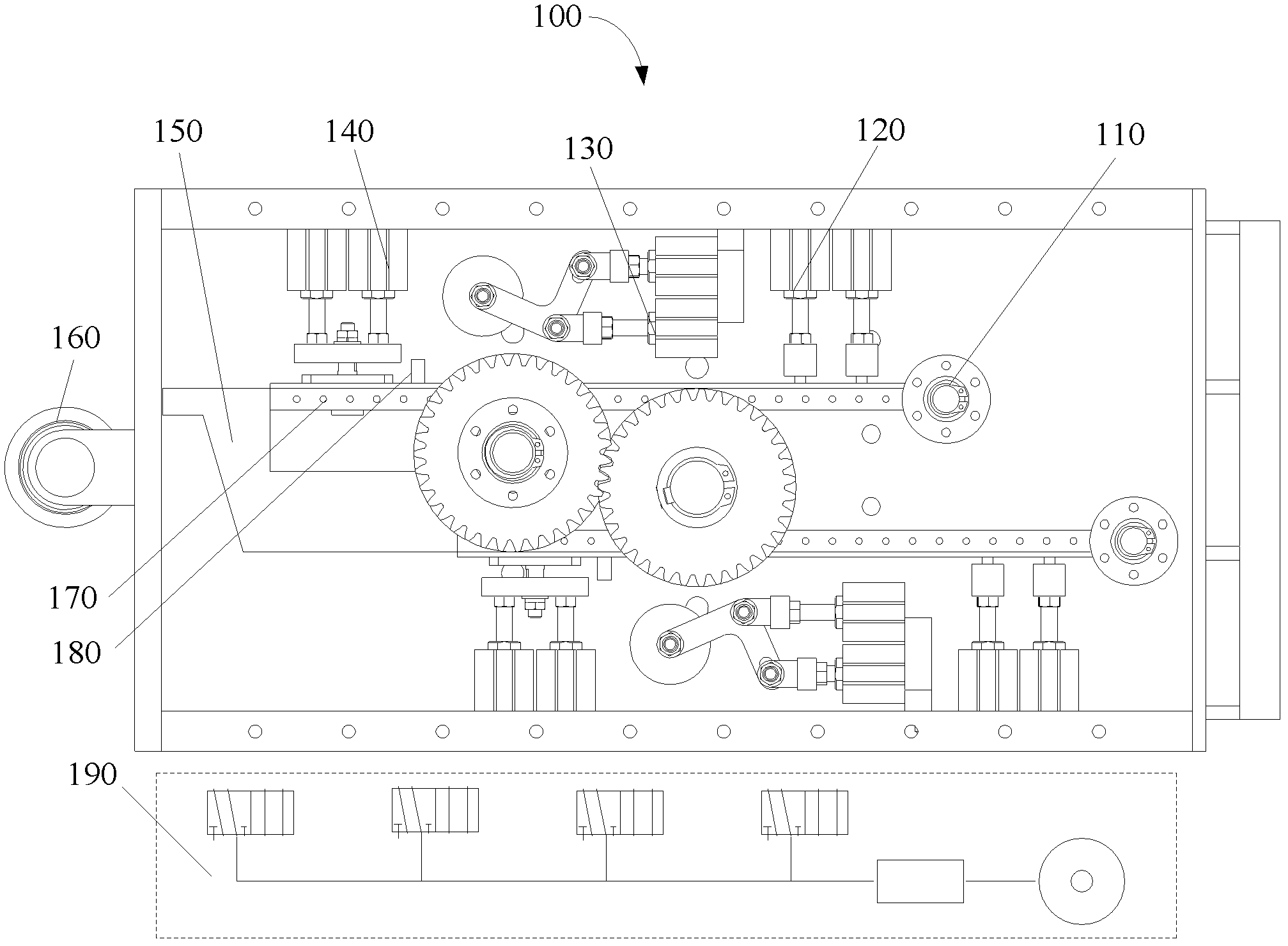
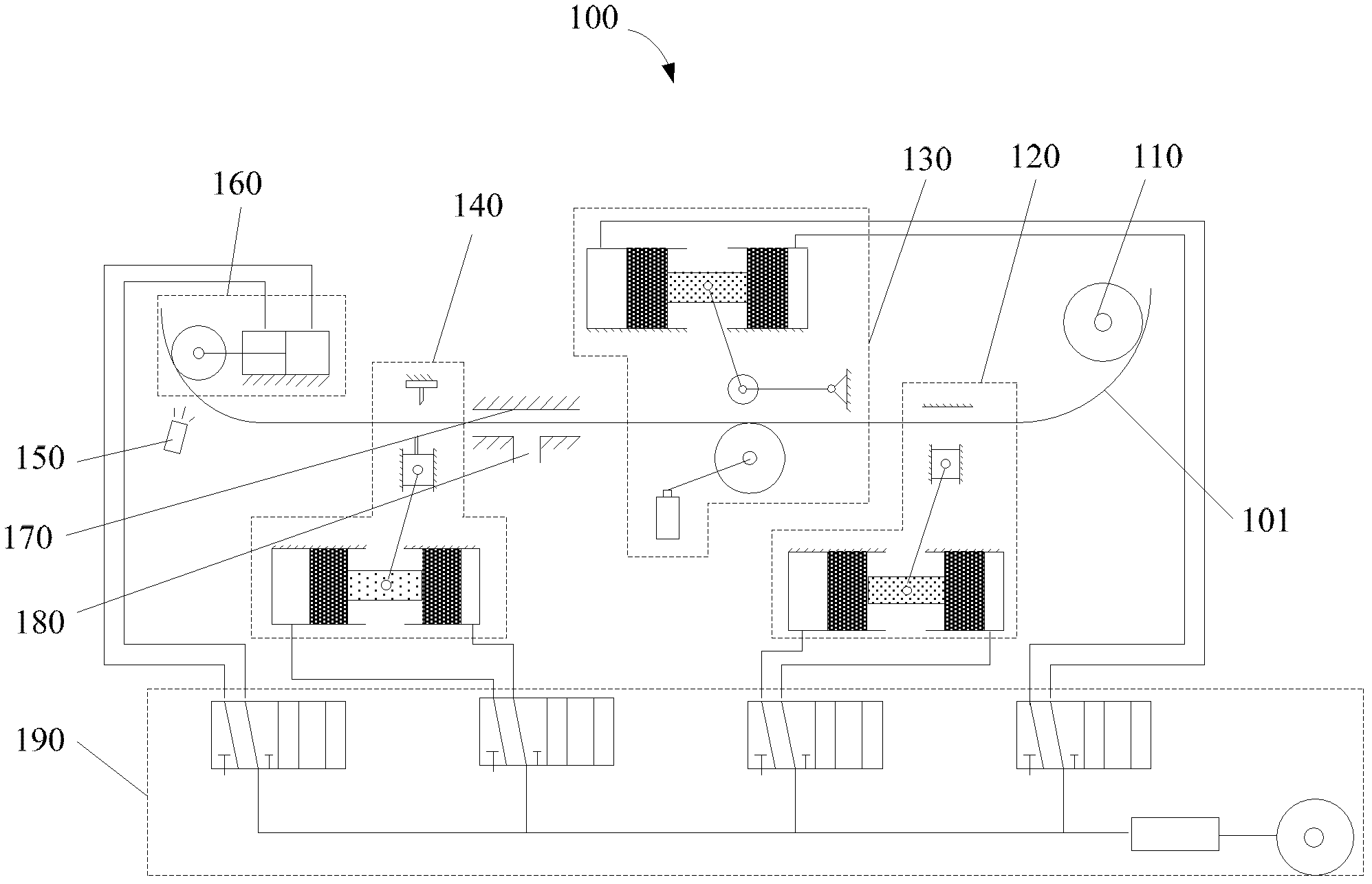
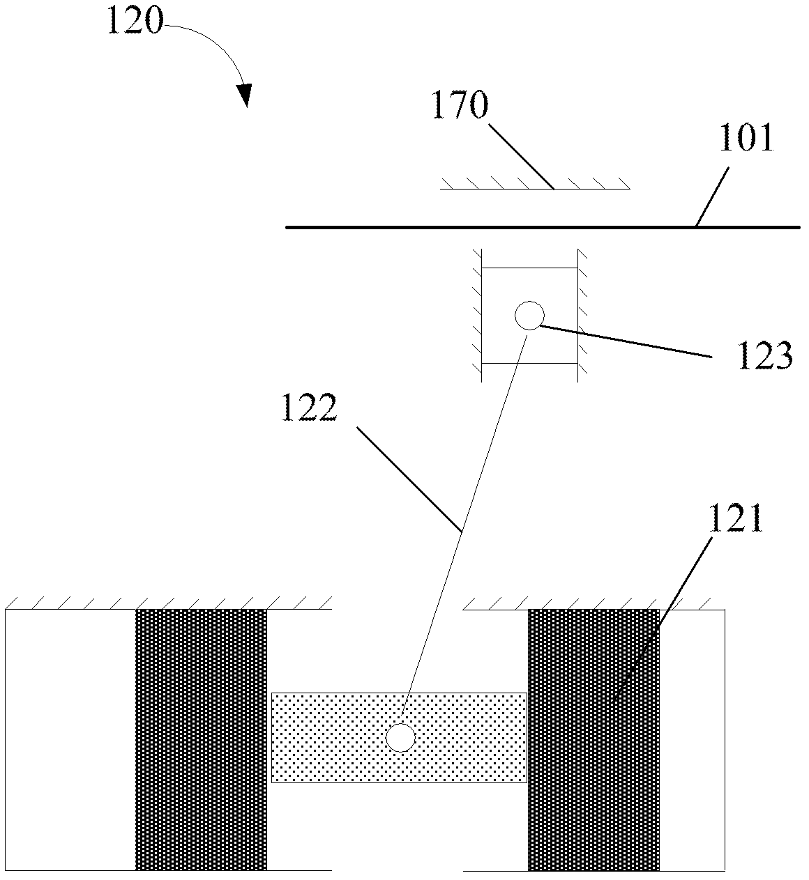
The invention relates to a placement head device comprising a tow channel, a guiding module, a fastening module, a re-conveying module, a shearing module, and a pressuring module. The guiding module is used for delivering the tows into the tow channel. The fastening module is used for fastening the tows by clamping before shearing. The re-conveying module is used for conveying the tows. The shearing module is used for shearing the tows. The pressuring module is used for compactly pressing the tows onto a product. A heating and gathering module is used for heating the tows and gathering the tows. According to the placement head device provided by the invention, through the cooperation of the modules, each stream of tows can be independently controlled, such that molding problems such as complicated curved surfaces, variable thicknesses, and reinforcement can be solved; product quality can be improved; and placement quality can be stabilized. Also, mechanized operations are adopted, such that placement efficiency is improved.

Description

【Technical field】 [0001] The invention relates to a carbon fiber laying equipment, in particular to a laying head device of the carbon fiber laying equipment. 【Background technique】 [0002] Composite fiber laying and forming technology is a fully automatic composite material processing technology developed as a reform of fiber winding and automatic tape laying technology. Filament winding equipment only has the related silk outlet, and does not have the function of laying head, which limits the fiber winding equipment to only aim at the rotary product, and finally wind the tow on the rotary product; the traditional one contains Larger flat rotary bodies are manufactured by manual laying, the production efficiency is very low, and the product quality is not stable. Carbon fiber laying equipment can theoretically lay mandrels of any shape. The laying head itself must complete the guiding, clamping, refeeding, shearing, heating and assembly of the tow, and finally lay the tow...

Claims


Application Information

Patent Timeline
IPC IPC(8): B29C70/54B29C70/30
Inventor 罗昌杰何凯荀大伟于文泽杜如虚
Owner SHENZHEN INST OF ADVANCED TECH CHINESE ACAD OF SCI
Why Eureka
Try Eureka