Knitting tool holder

A tool and support technology, used in warp knitting, knitting, textiles and papermaking, etc., can solve the problems of quality improvement and large wall thickness of knitting tool supports, and achieve the effect of improving stability and simplifying installation.

Inactive Publication Date: 2013-03-27
KARL MAYER TEXTILMASCHFAB GMBH
View PDF7 Cites 4 Cited by
  • Summary
  • Abstract
  • Description
  • Claims
  • Application Information

AI Technical Summary

Problems solved by technology

This results in a larger wall thickness for braided tool holders when using plastics or light me

Method used


Image

  • Knitting tool holder
  • Knitting tool holder
  • Knitting tool holder

Examples


Embodiment Construction

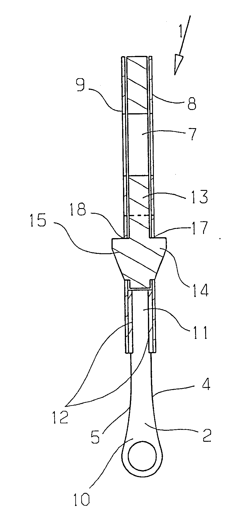
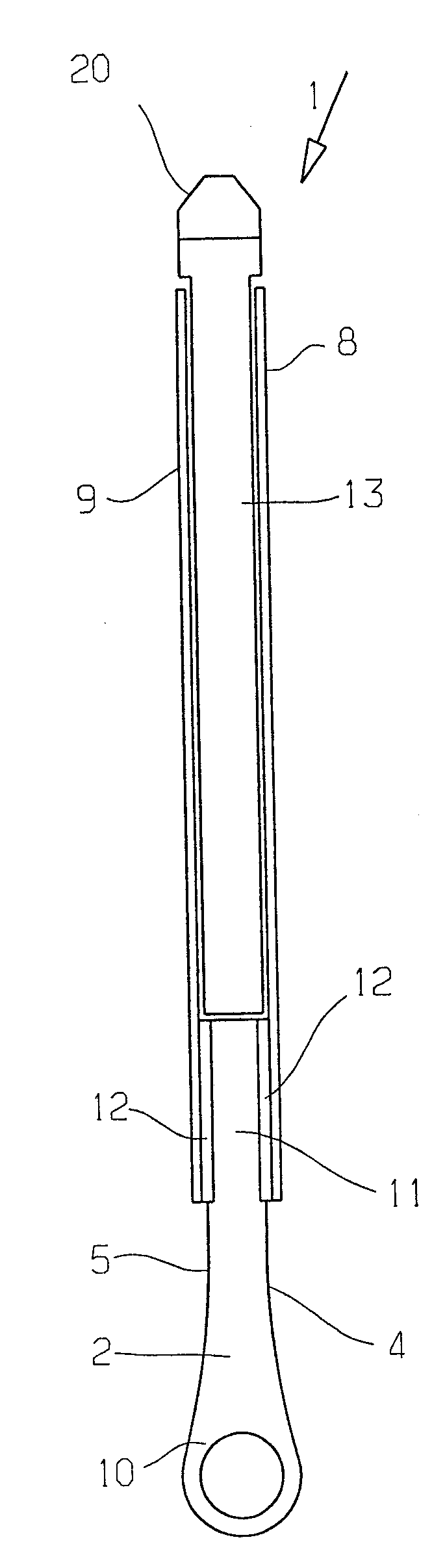
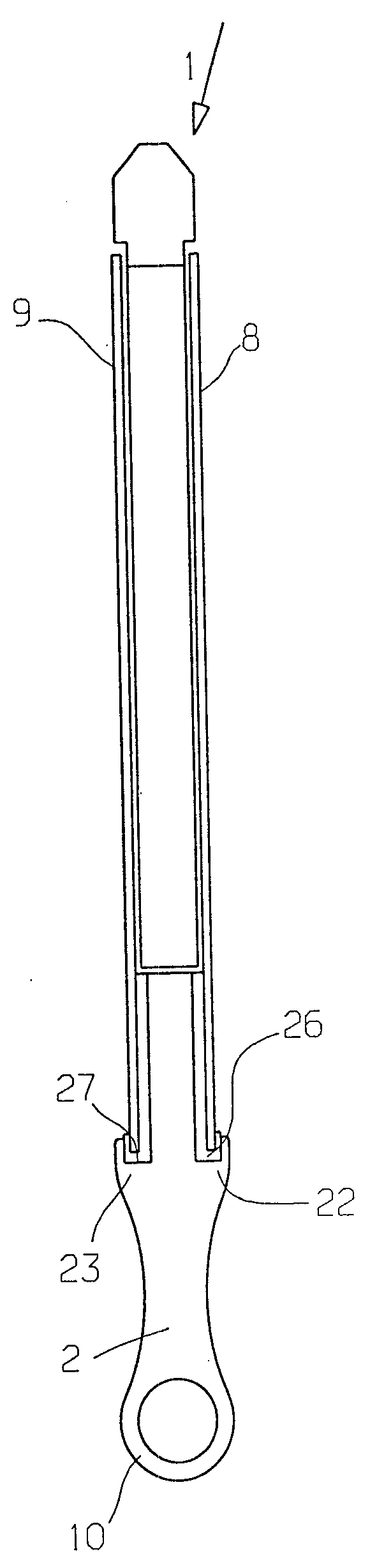
[0033] figure 1 A weaving tool holder 1 is shown with a plurality of weaving tools 2 which are arranged next to each other at a predetermined distance 3 from one another. Knitting Tool 2 in figure 1 Only the narrow side 4 is visible in . when will be in figure 1 If the narrow side 4 visible in is assigned to the front side, then the corresponding narrow side 5 is located on the rear side. The narrow sides 4, 5 point in opposite directions.

[0034] Depend on figure 2 and 3 It can be seen that the knitting tool 2 here in the form of an eye needle is of planar design. They can be stamped, for example, from sheet metal of corresponding thickness.

[0035] The weaving tool holder has two eyes 6 , 7 through which screws can be guided, and the weaving tool holder 1 can be screwed to a weaving tool bar, not shown in detail. The braiding tool holder 1 has a width of, for example, 1 or 2 inches. Since the eyes 6 , 7 can be arranged relatively far apart from one another, the k...


PUM

PropertyMeasurementUnit
Thicknessaaaaaaaaaa

Abstract

The tool holder (1) has a spacer (13) made from light metal or plastic, which is arranged between steel or plastic made cover plates (8,9) each with a thickness of about 0.1-0.8 mm. The knitting tools (2) are arranged parallel to each other with a predetermined distance. The front and rear narrow sides (4,5) of the knitting tools are bonded to the respective cover plates (8,9) through adhesive (12).

Description

technical field [0001] The invention relates to a weaving tool holder with a plurality of weaving tools, each of which has a working area, a fixing area and two narrow sides pointing in opposite directions, wherein the weaving tools are arranged parallel to one another and spaced apart from each other predetermined spacing. Background technique [0002] It is generally common in knitting machines to collect a plurality of knitting tools in one knitting tool holder. Weaving tool holders are often one or two inches (Zoll) wide and receive a corresponding number of weaving tools depending on the precision. [0003] The term "knitting tool" is used here as an abbreviation for those elements of a knitting machine, in particular a warp knitting machine, which are involved in the loop formation process during the production of the knitted fabric. The knitting tools not only involve the original knitting tools such as knitting needles, sliders, sinkers, etc., but also involve yarn...

Claims


Application Information

Patent Timeline
IPC IPC(8): D04B27/06
CPCD04B27/24D04B27/02D04B27/06D04B27/10
Inventor K.米斯塔
Owner KARL MAYER TEXTILMASCHFAB GMBH
Why Eureka
Try Eureka