
Pneumatic submerged pump

A pneumatic submersible pump, an integrated technology, applied in the direction of pumps, pump devices, non-variable pumps, etc., can solve the problems of poor pressure discharge effect, high exhaust flow speed, affecting production and processing, etc., and achieve drainage effect Good, low working noise effect

Inactive Publication Date: 2013-03-27
张玮
View PDF0 Cites 0 Cited by
  • Summary
  • Abstract
  • Description
  • Claims
  • Application Information

AI Technical Summary

Problems solved by technology

[0002] Pneumatic submersible pump power machines use compression control as the medium to compress the air into the cylinder, so that the cylinder reaches a certain air pressure, and the pressure generated will discharge the water. However, the higher the speed of the existing wind motor, the greater the power and the energy consumption. The larger the value, the higher the exhaust velocity
[0003] Existing pneumatic submersible pumps are widely used in controlling compressed air discharge, but high-frequency noise affects people's production and processing, and the pressure discharge effect is poor, which cannot meet the existing processing conditions

Method used


Image

  • Pneumatic submerged pump

Examples


Embodiment Construction

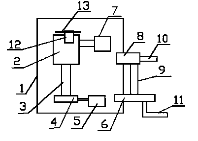
[0010] In this example, refer to figure 1 As shown, a pneumatic submersible pump of the present invention includes an integrated casing 1, a cylinder 2 arranged on the integrated casing 1, a main shaft 3 arranged on the cylinder 2, and a shaft connected to the main shaft 3 The impeller 4, the integrated housing 1 is also provided with a water inlet 5, a water outlet 6, an air inlet 7 and an air outlet 8, the water outlet 6 is connected to a drain pipe 11, and the air outlet 8 is connected to a drain The air pipe 10, the air outlet 8 and the water outlet 6 are connected to each other, and the connection between the air outlet 8 and the water outlet 6 is provided with a sealed connection pipe 9 .

[0011] A rotor 12 is arranged on the top of the cylinder 2 , and vanes 13 are arranged on the rotor 12 , and the cylinder 2 communicates with the air inlet 7 .

[0012] The impeller 4 communicates with the water inlet 5 .

[0013] The beneficial effect of the pneumatic submersible p...


PUM


Abstract

The invention discloses a pneumatic submerged pump. The pneumatic submerged pump comprises an integrated shell, an air cylinder, a main shaft and an impeller, wherein the air cylinder is arranged on the integrated shell, the main shaft is arranged on the air cylinder, the impeller is connected onto the main shaft, the integrated shell is also provided with a water inlet, a water outlet, an air inlet and an air outlet, the water outlet is connected with a drain pipe, the air outlet is connected with an exhaust pipe, the air outlet and the water outlet are connected with each other, and a sealing connecting pipe is arranged at a connecting part between the air outlet and the water outlet; and according to the technical scheme, a rotor drives the impeller to rotate to compress air, generated power drives the main shaft to rotate, the main shaft drives the impeller to work, and the pneumatic submerged pump has good water drainage effect and low operating noise.

Description

technical field [0001] The invention relates to a pneumatic submersible pump. Background technique [0002] Pneumatic submersible pump power machines use compression control as the medium to compress the air into the cylinder, so that the cylinder reaches a certain air pressure, and the pressure generated will discharge the water. However, the higher the speed of the existing wind motor, the greater the power and the energy consumption. The larger the value is, the higher the exhaust flow velocity is. [0003] Existing pneumatic submersible pumps are widely used in controlling compressed air discharge, but high-frequency noise affects people's production and processing, and the pressure discharge effect is poor, which cannot meet the existing processing conditions. Contents of the invention [0004] The technical problem to be solved by the present invention is to provide a pneumatic submersible pump with low working noise and improved drainage flow. [0005] In order to...

Claims


Application Information

Patent Timeline
Patent Type & Authority Applications(China)
IPC IPC(8): F04D13/04
Inventor 张玮
Owner 张玮
Learn More