Heat exchanger system of small type air conditioner for cabin
A small air conditioner and heat exchange system technology, applied in the field of heat exchange system, can solve the problems that the cooling capacity of the air conditioner cannot meet the needs of the cabin, the environment in the cabin cannot be improved, and the air pressure of the air outlet of the air conditioner is high, and the structure is compact, The effect of low cost and increased cooling capacity
- Summary
- Abstract
- Description
- Claims
- Application Information
AI Technical Summary
Problems solved by technology
Method used
Image
Examples
Embodiment 1
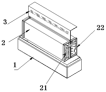
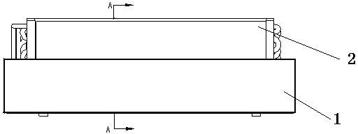
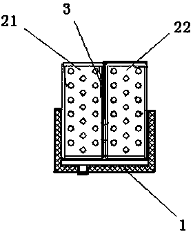
[0028] Such as figure 1 , figure 2 , image 3 As shown, the lower part of the heat exchanger 2 is arranged in the deep water tank 1, and the heat exchanger 2 is an integral body composed of the first evaporator 21 and the second evaporator 22 connected in parallel through respective side plates; the first evaporator 21 and the second evaporator The middle upper part of the second evaporator 22 is provided with an L-shaped baffle plate 3, the horizontal section of the baffle plate 3 is placed on the upper end surface of the second evaporator 22 to avoid a short circuit of the flow channel, and the vertical section of the baffle plate 3 is placed on the first The evaporator 21 is separated from the upper part of the second evaporator 22, and the vertical section of the baffle plate 3 is provided with ventilation holes to improve local heat exchange. The heights of the deep water tank 1 and the baffle plate 3 are both slightly greater than half of the height of the heat exchan...
Embodiment 2
[0030] Such as Figure 4 Shown is a schematic structural diagram of the first case of the heat exchange system of the present invention. The lower part of the heat exchanger 2 is arranged in the deep water tank 1, and the heat exchanger 2 is composed of the first evaporator 21 and the second evaporator 22 through respective side plates. A whole formed in parallel; the upper middle of the first evaporator 21 and the second evaporator 22 is provided with an L-shaped baffle 3, and the horizontal section of the baffle 3 is placed on the upper end surface of the second evaporator 22 to avoid flow passages short circuit. The fan 4 is placed behind the heat exchanger 2, that is, on one side of the second evaporator 22, thereby realizing the control of the height of the air conditioner and becoming an ultra-thin top-mounted air conditioner to adapt to the space in the low-profile cabin.
[0031] Of course, the blower fan 4 can also be placed in front of the heat exchanger 2, that is,...
Embodiment 3
[0033] Such as Figure 5 Shown is a schematic structural diagram of the second case of the heat exchange system of the present invention. The lower part of the heat exchanger 2 is arranged in the deep water tank 1, and the heat exchanger 2 is composed of the first evaporator 21 and the second evaporator 22 through respective side plates. A whole formed in parallel; the upper middle of the first evaporator 21 and the second evaporator 22 is provided with an L-shaped baffle 3, and the horizontal section of the baffle 3 is placed on the upper end surface of the second evaporator 22 to avoid flow passages short circuit. The blower fan 4 is placed above the heat exchanger 2, thereby realizing the control of the width of the air conditioner, and becoming an ultra-thin wall-mounted air conditioner to adapt to the narrow cabin space.
PUM
 Abstract
Description
Claims
Application Information
 - R&D
- Intellectual Property
- Life Sciences
- Materials
- Tech Scout
- Unparalleled Data Quality
- Higher Quality Content
- 60% Fewer Hallucinations
Browse by: Latest US Patents, China's latest patents, Technical Efficacy Thesaurus, Application Domain, Technology Topic, Popular Technical Reports.
© 2025 PatSnap. All rights reserved.Legal|Privacy policy|Modern Slavery Act Transparency Statement|Sitemap|About US| Contact US: help@patsnap.com


