Supercharge Your Innovation With Domain-Expert AI Agents!

Novel electromagnetic accelerometer structure

An accelerometer and electromagnetic technology, applied in the direction of measuring acceleration, velocity/acceleration/shock measurement, acceleration measurement using inertial force, etc., can solve the problem of difficult control, increasing the nonlinearity of the accelerometer, and affecting the improvement and stability of resolution To achieve the effect of improving the uniformity, increasing the axial smooth area, reducing nonlinearity and disturbance torque

Inactive Publication Date: 2013-03-27
TIANJIN NAVIGATION INSTR RES INST
View PDF6 Cites 9 Cited by
  • Summary
  • Abstract
  • Description
  • Claims
  • Application Information

AI Technical Summary

Problems solved by technology

This effect can be avoided only when the magnetic induction of the two permanent magnets is exactly the same, but it is difficult to control in actual work
[0005] 2. In order to improve the magnetic induction intensity, the thickness of the magnetic guide plate should not be too large, the smooth area of ​​the working air gap magnetic induction intensity will be limited, and it is possible to make part of the torquer coil work in the non-smooth area of ​​the air gap magnetic induction intensity, so that the quartz pendulum component The "increase and decrease magnetic effect" generated by motion will increase the non-linearity of the accelerometer, affecting the improvement of resolution and stability

Method used


Image

  • Novel electromagnetic accelerometer structure
  • Novel electromagnetic accelerometer structure

Examples


Embodiment Construction

[0021] The present invention will be further described in detail below through the specific examples, the following examples are only descriptive, not restrictive, and cannot limit the protection scope of the present invention with this.

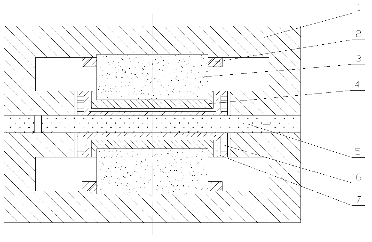
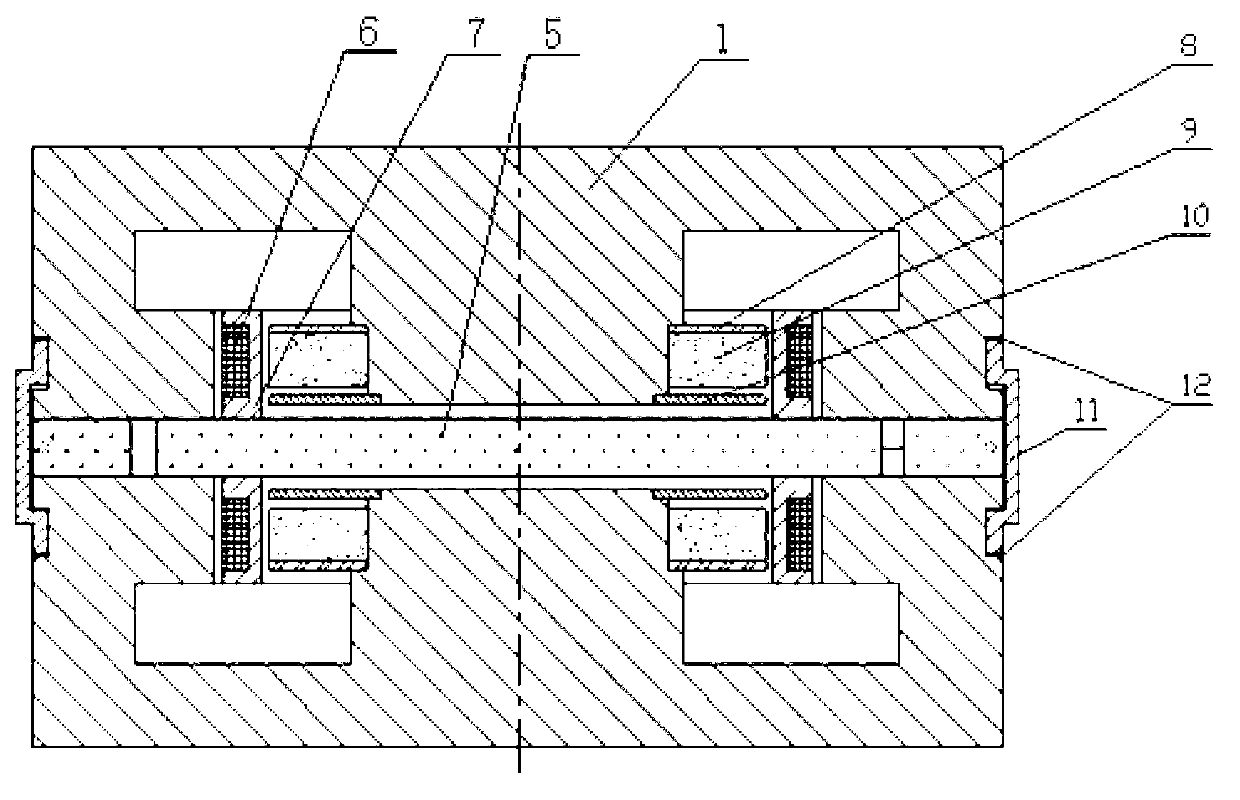
[0022] A novel electromagnetic accelerometer structure includes a quartz pendulum assembly and a magnetic conduction ring assembly, and the quartz pendulum assembly and the magnetic conduction ring assembly are installed in a housing assembly (not shown in the figure). The quartz pendulum assembly includes a quartz pendulum 5 and a torquer coil assembly. The torquer coil assembly includes a torque coil 6 and a torque coil bobbin 7. The torque coils are equidistant and parallel wound on the outer surface of the torque coil bobbin to form a torquer coil assembly. The coil assembly and the magnetic ring assembly are used in pairs, and the mirror image is installed on the upper and lower sides of the quartz pendulum. The lead wire of the torque c...


PUM


Abstract

The invention relates to a novel electromagnetic accelerometer structure which comprises a quartz pendulous reed component, magnetic conductance ring components and a casing component. The electromagnetic accelerometer structure is of a push-pull type. A torquer coil component and the magnetic conductance ring components are used in pairs, and mirrors are arranged above and under a quartz pendulous reed symmetrically. Upper and lower magnetic conductance rings are connected through a connection ring by a laser welding method. A cavity of each of the magnetic conductance ring components is provided with a thermomagnetic compensation ring, a permanent magnet radiation ring and an electromagnetic shielding ring which are coaxially and successively mounted on a central shaft of a magnetic conductance ring. The novel electromagnetic accelerometer structure is designed on the basis of the successful design of small permanent magnet radiation rings. The novel electromagnetic accelerometer structure has the advantages that working air-gap magnetic fields are uniform, an axial smooth area is large, flux leakage of a quartz pendulous reed area is low, and the impact resistance is high. Accordingly, the bias of an accelerometer can be reduced, and the measuring range and the stability are improved. The novel electromagnetic accelerometer structure is applicable to high-precision inertial navigation and guidance measurement systems and occasions with wide-range acceleration measurement and impact resistant requirements.

Description

technical field [0001] The invention relates to an electromagnetic accelerometer in the field of measuring instruments, in particular to an electromagnetic accelerometer suitable for high-precision inertial navigation and guidance measurement systems, large-scale acceleration measurement and shock resistance requirements. Background technique [0002] At present, the structure of the electromagnetic accelerometer is introduced in detail in the US Patent (Patent No. 4250757). figure 1 shown. It includes a magnetic conduction ring 1 , a thermomagnetic compensation ring 2 , a cylindrical permanent magnet 3 , a magnetic conduction plate 4 , a quartz pendulum 5 , a torque coil 6 , and a torque coil skeleton 7 . The magnetic permeable ring, the thermomagnetic compensating ring, the cylindrical permanent magnet and the magnetic permeable plate form the magnetic permeable ring assembly. The quartz pendulum plate, the torquer coil and the bobbin form the quartz pendulum plate assem...

Claims


Application Information

Patent Timeline
IPC IPC(8): G01P15/125G01P15/13
Inventor 刘晓东聂鲁燕李德才于洪宇赵丙权贾子奇
Owner TIANJIN NAVIGATION INSTR RES INST
Features
  • R&D
  • Intellectual Property
  • Life Sciences
  • Materials
  • Tech Scout
  • Unparalleled Data Quality
  • Higher Quality Content
  • 60% Fewer Hallucinations
Learn More