
Foldable handle

A handle and handle rod technology, which is applied in the field of photographic equipment, can solve the problems of inconvenience and cumbersome operation, and achieve the effect of large rotational torque, enhanced connection strength, and enhanced connection

Active Publication Date: 2013-03-27
GUANGDONG SIRUI OPTICAL CO LTD
View PDF8 Cites 4 Cited by
  • Summary
  • Abstract
  • Description
  • Claims
  • Application Information

AI Technical Summary

Problems solved by technology

[0005] For this reason, the technical problem to be solved by the present invention lies in a foldable handle in the prior art, which is cumbersome and inconvenient to operate, and further provides a foldable handle with easy operation and good hand feeling

Method used


Image

  • Foldable handle
  • Foldable handle
  • Foldable handle

Examples


Embodiment 1

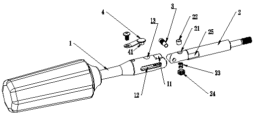
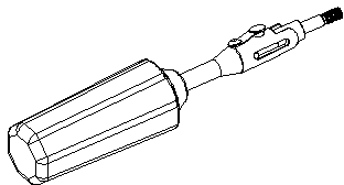
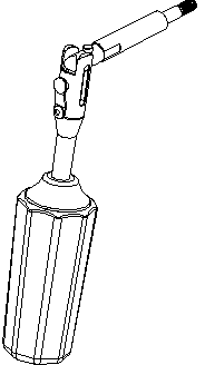
[0029] Such as figure 1 As shown, a foldable handle described in Embodiment 1 includes a handle bar 1, a locking bar 2 that is rotatably connected to the handle bar 1 through a rotating shaft 3, and the linearly connected state. The locking structure for locking the handle rod 1 and the locking rod 2; it also includes an axial telescopic structure, and the axial telescopic structure includes an axial accommodation cavity 11 formed at the connecting end of the handle rod 1, so that A chute 12 extending in the axial direction is formed on the side wall of the accommodating cavity 11 for inserting the end of the rotating shaft 3, and the connecting end of the locking rod 2 extends into the accommodating cavity 11 and slides back and forth; and The shape of the port of the accommodating cavity 11 is suitable for the rotation and folding of the locking rod 2 around the rotating shaft 3. In this embodiment, the chute 12 is preferably arranged in two symmetrically; The backstop thro...

Embodiment 2

[0034] Such as figure 2As shown, in this embodiment, a groove 14 is formed on the side wall where the backstop through hole 13 of the handle bar 1 is located, which is suitable for pressing the pad of a finger, to replace the elastic button in Embodiment 1. structure, when the handle is folded, it is only necessary to press the anti-retraction pin 22 to make it withdraw from the anti-retraction through hole 13, the structure is simpler, and the hand feeling is more comfortable.


PUM


Abstract

The invention discloses a foldable handle. The handle comprises a handle rod, a locking rod which is connected to the handle rod through a rotary shaft in a rotary mode, a locking structure which is used for locking the handle rod and the locking rod which are in the linear connection state and an axial telescopic structure, wherein the axial telescopic structure comprises an axial containing cavity which is formed at the connection end of the handle rod, a chute which extends axially and in which a rotary shaft end is inserted is formed on the side wall of the containing cavity, the connection end of the locking rod extends into the containing cavity to slide back and forth, the shape of the end of the containing cavity is matched to the locking rod which rotates and is folded round the rotary shaft, the locking structure comprises a stopping through hole which is formed on the side wall of the handle rod, a stopping shaft pin hole formed on the locking rod, a stopping pin shaft and a bias part, and the stopping pin shaft and the bias part are arranged in the stopping pin shaft hole. The handle can be folded and can be fixed to the linear shape, the operation is facilitated and the touch is comfortable.

Description

technical field [0001] The invention relates to the technical field of photographic equipment, in particular to a foldable handle for locking a rotating structure on a photography platform or a photography tripod. Background technique [0002] In life, the use of photographic equipment is more and more extensive. People like to carry photographic equipment when they go out to take pictures on the road. In order to improve the convenience of carrying photographic equipment, people change the handle on the photographic equipment into a foldable handle. The handle can be folded up when carrying, thereby reducing the space occupied by photographic equipment. [0003] For example, the Chinese patent document CN201583773U discloses a foldable handle, which includes a handle bar and a fixing part. The handle bar also includes a connecting part and a handle part, and the connecting part and the handle part are foldably and flexibly connected. The handle portion is fixed into a stra...

Claims


Application Information

Patent Timeline
IPC IPC(8): G03B17/56
Inventor 李杰
Owner GUANGDONG SIRUI OPTICAL CO LTD
Learn More