
Liquid injection device and liquid injection method for battery electrolyte

A liquid injection device and electrolyte technology, which is applied to battery pack parts, circuits, electrical components, etc., can solve the problems of low liquid injection accuracy, long liquid injection time, large deviation, etc., and achieve accurate liquid injection and rapid liquid injection fast effect

Active Publication Date: 2015-04-22
DONGGUAN HONBRO LI BATTERY EQUIP TECH
View PDF7 Cites 0 Cited by
  • Summary
  • Abstract
  • Description
  • Claims
  • Application Information

AI Technical Summary

Problems solved by technology

In the prior art, there are two main problems with the battery electrolyte: first, the injection time is long; second, the injection accuracy is low
However, on the one hand, since the gauge is installed on the liquid injection pipeline, there is a section of liquid injection pipeline and gas-liquid switching valve between the gauge and the battery. Therefore, affected by the hysteresis of the electrolyte flow, even if the gauge can accurately control , there will be a deviation between the amount of electrolyte injected into the battery and the control amount of the meter, and the farther the meter is from the battery, the greater the deviation will be; on the other hand, the battery electrolyte injection machine will , and the residual electrolyte in the liquid injection port in contact with the battery cannot be cleaned in time. In this way, not only the electrolyte is easily bonded to the inner wall of the liquid injection port, it needs to be cleaned frequently, but the electrolyte is also very easy to drip out from the liquid injection port. , affect the working environment, and even affect the accuracy of the next injection

Method used


Image

  • Liquid injection device and liquid injection method for battery electrolyte
  • Liquid injection device and liquid injection method for battery electrolyte
  • Liquid injection device and liquid injection method for battery electrolyte

Examples


Embodiment 1

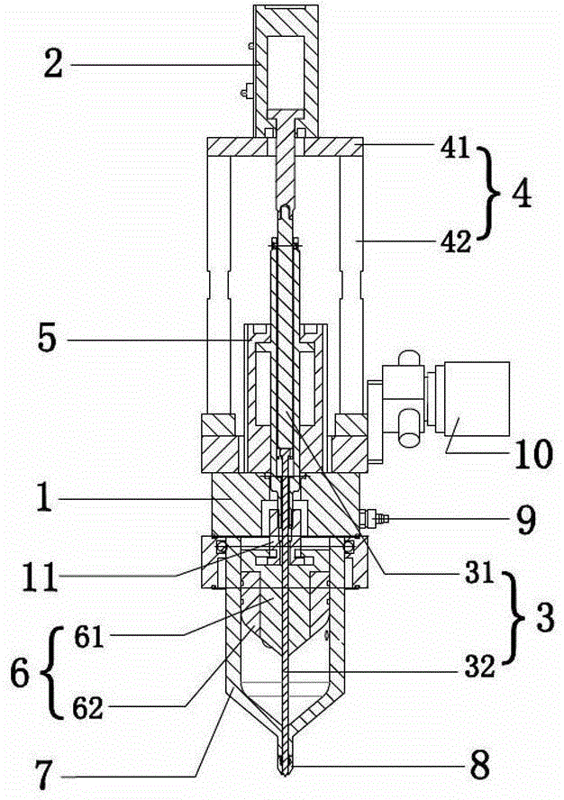
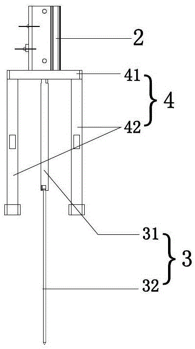
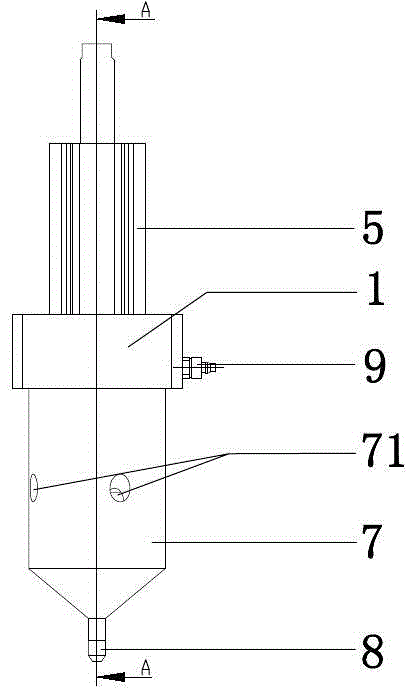
[0025] Embodiment one: if figure 1 , figure 2 , image 3 and Figure 4 As shown, in this embodiment, the battery electrolyte injection device includes a fixed seat 1, a plugging cylinder 2, a plugging rod 3, a plugging rod frame 4, a liquid injection cylinder 5, a liquid injection piston 6, and an electrolyte transfer cup 7. The liquid injection cylinder 6 is installed on the upper side of the fixed seat 1, the plugging cylinder 2 is located directly above the liquid injection cylinder 6, and the plugged cylinder 2 is installed on the fixed seat 1 through the plugging frame 4; The electrolyte transfer cup 7 is installed on the lower side of the fixed seat 1, the lower end of the electrolyte transfer cup 7 is provided with a sealing head 8, and the liquid injection piston 6 is plugged in the liquid injection transfer cup 7; the fixed seat 1, injection The liquid piston 6, the sealing head 8 and the piston rod of the liquid injection cylinder 5 are all provided with a pluggi...

Embodiment 2

[0031] Embodiment 2: The battery electrolyte injection method using the above-mentioned battery electrolyte injection device includes the following steps:

[0032] a. Transfer the battery electrolyte to the electrolyte transfer cup of the above-mentioned battery electrolyte injection device;

[0033] b. The plugging cylinder drives the plugging rod to be pulled out from the plugging hole of the sealing head, so that the electrolyte can flow down through the plugging hole of the sealing head;

[0034] c. The liquid injection cylinder drives the liquid injection piston to move downward, and the liquid injection piston squeezes the electrolyte in the electrolyte transfer cup and enters the battery through the blocking rod hole of the sealing head;

[0035] d. The plugging rod cylinder drives the plugging rod to extend down into the plugging rod hole of the sealing head, so that the plugging rod hole of the sealing head is closed, and at the same time, the plugging rod squeezes ou...


PUM


Abstract

The invention discloses a liquid injection device and a liquid injection method for a battery electrolyte, wherein the liquid injection device for the battery electrolyte comprises a fixed seat, a stop rod cylinder, a stop rod, a stop rod frame, a liquid injection cylinder, a liquid injection piston and an electrolyte transfer cup; the liquid injection cylinder is fixedly mounted on the upper side of the fixed seat, the stop rod cylinder is positioned right above the liquid injection cylinder, and the stop rod cylinder is mounted on the fixed seat through the stop rod frame; the electrolyte transfer cup is mounted on the lower side of the fixed seat, a sealing head is arranged at the lower end of the electrolyte transfer cup, and the liquid injection piston is plugged into the liquid injection transfer cup; and stop rod holes are arranged in the fixed seat, the liquid injection piston, the sealing head and the piston rod of the liquid injection cylinder, the piston rod of the stop rod cylinder is connected with the stop rod, and the stop rod sequentially penetrates through the stop rod holes of the piston rod of the liquid injection cylinder, the fixed seat and the liquid injection piston from top to bottom and is matched with the sealing head at the lower end of the liquid injection transfer cup. The liquid injection device disclosed by the invention has the advantages of short liquid injection time and very high liquid injection precision, and can be used for automatically clearing the residual electrolyte in a liquid injection port.

Description

technical field [0001] The invention relates to the technical field of battery manufacturing, in particular to a battery electrolyte injection device and a liquid injection method. Background technique [0002] With the development of society, various electronic devices are used more and more widely, and the demand for batteries, especially lithium-ion batteries, is increasing year by year. The outer casing of the battery is generally divided into steel casing, aluminum casing and soft non-metallic casing. During the manufacturing process of the battery, the electrolyte needs to be injected into the outer casing. In the prior art, there are two main problems with the battery electrolyte: first, the injection time is long; and second, the injection accuracy is low. [0003] Chinese patent 201020198131.2 discloses a battery electrolyte injection machine, which includes a liquid storage tank, a liquid injection pipe, and a battery. There is a gas-liquid switching valve. When ...

Claims


Application Information

Patent Timeline
Patent Type & Authority Patents(China)
IPC IPC(8): H01M2/36
CPCY02E60/10
Inventor 喻世民童安南廖均克樊树根彭清华
Owner DONGGUAN HONBRO LI BATTERY EQUIP TECH
Features
  • Generate Ideas
  • Intellectual Property
  • Life Sciences
  • Materials
  • Tech Scout
  • Unparalleled Data Quality
  • Higher Quality Content
  • 60% Fewer Hallucinations
Learn More