
Machining equipment for improving machining precision of injection mold and machining method thereof

A technology of processing precision and injection mould, which is applied in the field of processing equipment to improve the processing precision of injection moulds, can solve the problems that the injection precision needs to be improved and there is no auxiliary detection, and achieve the effect of reducing air bubbles and improving the precision

Inactive Publication Date: 2021-02-26
嘉兴天行健精密模具有限公司
View PDF4 Cites 3 Cited by
  • Summary
  • Abstract
  • Description
  • Claims
  • Application Information

AI Technical Summary

Problems solved by technology

[0004] The processing equipment for improving the processing precision of injection molds has the following disadvantages: 1. There are parts that can improve the uniform and rapid flow of injection materials into the cavity, and the accuracy of injection needs to be improved; 2. There is no pressure and conveying heat that can close the molds. Parts for auxiliary detection of the temperature of the molten material

Method used


Image

  • Machining equipment for improving machining precision of injection mold and machining method thereof
  • Machining equipment for improving machining precision of injection mold and machining method thereof
  • Machining equipment for improving machining precision of injection mold and machining method thereof

Examples


Embodiment 1

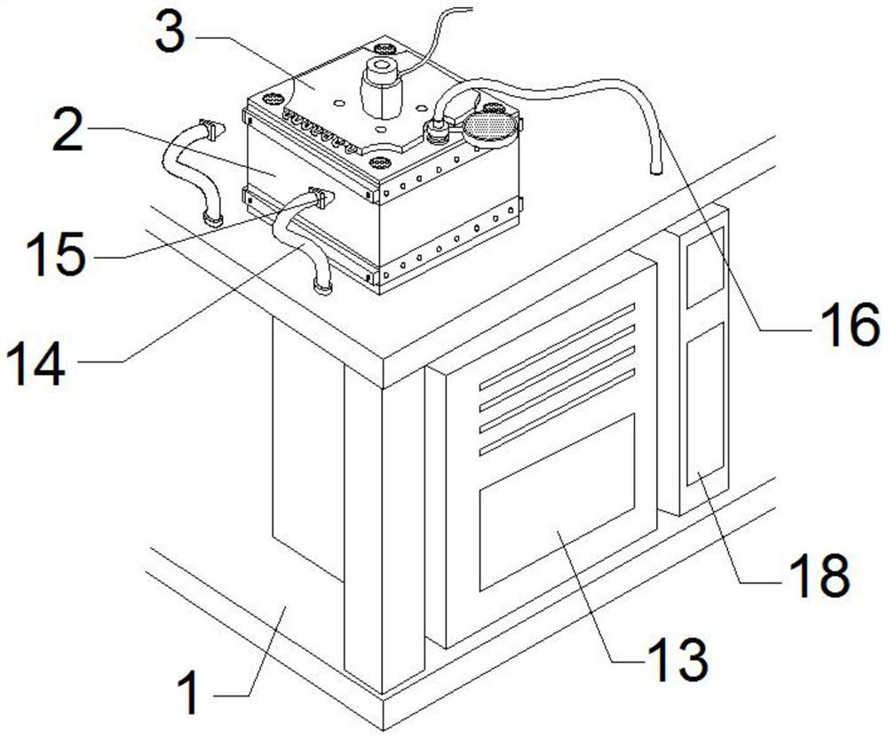
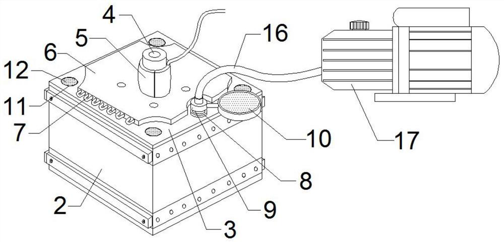
[0031] Such as Figure 1-3 As shown, a processing equipment for improving the processing accuracy of injection molds includes a processing frame 1, a lower mold 2, an upper mold 3, a cooling plate 6, a pressure sensor 26 and a temperature sensor 27, and the top of the processing frame 1 is fixedly installed with a lower mold 2. The upper cover of the lower mold 2 is provided with an upper mold 3, and the middle part of the top of the upper mold 3 is provided with a material injection port 4, and the two sides of the outer periphery of the bottom end of the said material injection port 4 are respectively clamped with electric heating sleeves 5, so The top of the upper mold 3 and the outer cover of the injection port 4 are provided with a cooling plate 6, and the inner serpentine is arranged with a cooling copper tube 7, and the top side of the upper mold 3 is provided with an exhaust nozzle 8. A one-way valve 9 is sleeved on the exhaust nozzle 8, and an air pressure sensor 10 i...

Embodiment 2

[0054] Such as Figure 1-3 As shown, a processing equipment for improving the processing accuracy of injection molds includes a processing frame 1, a lower mold 2, an upper mold 3, a cooling plate 6, a pressure sensor 26 and a temperature sensor 27, and the top of the processing frame 1 is fixedly installed with a lower mold 2. The upper cover of the lower mold 2 is provided with an upper mold 3, and the middle part of the top of the upper mold 3 is provided with a material injection port 4, and the two sides of the outer periphery of the bottom end of the said material injection port 4 are respectively clamped with electric heating sleeves 5, so The top of the upper mold 3 and the outer cover of the injection port 4 are provided with a cooling plate 6, and the inner serpentine is arranged with a cooling copper tube 7, and the top side of the upper mold 3 is provided with an exhaust nozzle 8. A one-way valve 9 is sleeved on the exhaust nozzle 8, and an air pressure sensor 10 i...

Embodiment 3

[0073]Such as Figure 1-3 As shown, a processing equipment for improving the processing accuracy of injection molds includes a processing frame 1, a lower mold 2, an upper mold 3, a cooling plate 6, a pressure sensor 26 and a temperature sensor 27, and the top of the processing frame 1 is fixedly installed with a lower mold 2. The upper cover of the lower mold 2 is provided with an upper mold 3, and the middle part of the top of the upper mold 3 is provided with a material injection port 4, and the two sides of the outer periphery of the bottom end of the said material injection port 4 are respectively clamped with electric heating sleeves 5, so The top of the upper mold 3 and the outer cover of the injection port 4 are provided with a cooling plate 6, and the inner serpentine is arranged with a cooling copper tube 7, and the top side of the upper mold 3 is provided with an exhaust nozzle 8. A one-way valve 9 is sleeved on the exhaust nozzle 8, and an air pressure sensor 10 is...


PUM


Abstract

The invention discloses machining equipment for improving machining the precision of an injection mold and a machining method thereof. The machining equipment comprises a machining frame, a lower mold, an upper mold, a cooling plate, a pressure sensor and a temperature sensor, the lower mold is fixedly mounted at the top of the machining frame, the upper mold is arranged on an upper cover of the lower mold, and a material injection opening is formed in the middle of the top of the upper mold. The sealing pressure intensity between molds is detected through sensing detection of the multiple sets of sensors, so that the phenomenon that injected materials rapidly flow into gaps between cloth and mold grooves, and hollowing bubbles are greatly reduced are too loose and overflow is generated isavoided, negative-pressure air suction is conducted in the dies, injected materials can rapidly flow into gaps between cloth and die grooves, the phenomenon of hollowing bubbles is greatly reduced can be avoided, and the machining precision is effectively improved; and the temperature sensor is used for detecting the temperature of the material injection opening, after the temperature of the material injection opening is lower than a set value, a processor starts an electric heating sleeve to heat the material injection opening, and thus, the situation that normal circulation cannot be achieved due to the too low melting material injection temperature is avoided.

Description

technical field [0001] The invention belongs to the technical field of injection molds, and in particular relates to a processing equipment and a processing method for improving the processing precision of injection molds. Background technique [0002] Injection mold means that in the heating barrel of the injection machine, the plastic is heated and melted, pushed by the screw or ducer, enters the mold cavity through the nozzle and the gating system of the mold, and the plastic is hardened and shaped in the cavity; the injection mold is used for thermoplastics The molding of products is used for the molding of thermosetting plastics. When the current injection mold is injected, the phenomenon of uneven injection such as air bubbles and hollowing is prone to occur inside the mold cavity. The accuracy of the material needs to be improved, and there is no component that can assist in the detection of the closing pressure between the molds and the temperature of the hot melt ma...

Claims


Application Information

Patent Timeline
IPC IPC(8): B29C45/03B29C45/17B29C45/73B29C45/76
CPCB29C45/03B29C45/17B29C45/1701B29C45/7337B29C45/76B29C2045/1784B29C2945/76006B29C2945/76387
Inventor 顾深锋顾深群
Owner 嘉兴天行健精密模具有限公司
Learn More