Sampling volume controllable micro-fluidic chip sieving electrophoresis analytical method

A technology of microfluidic chip and electrophoresis analysis, which is applied in separation methods, material analysis through electromagnetic means, and material analysis, etc., can solve the problems of fixed sample volume and slow sample injection speed, and achieve fast sample injection speed and negative The effect of stable pressure and convenient operation

Inactive Publication Date: 2008-07-09
ZHEJIANG UNIV
View PDF0 Cites 5 Cited by
  • Summary
  • Abstract
  • Description
  • Claims
  • Application Information

AI Technical Summary

Problems solved by technology

Overcome the shortcomings of the current microfluidic chip sieving electrophoresis with fixed sample injection volume, slow sample injection speed, multi-channel power supply and complex control system for sample injection

Method used


Image

  • Sampling volume controllable micro-fluidic chip sieving electrophoresis analytical method
  • Sampling volume controllable micro-fluidic chip sieving electrophoresis analytical method

Examples


Embodiment 1

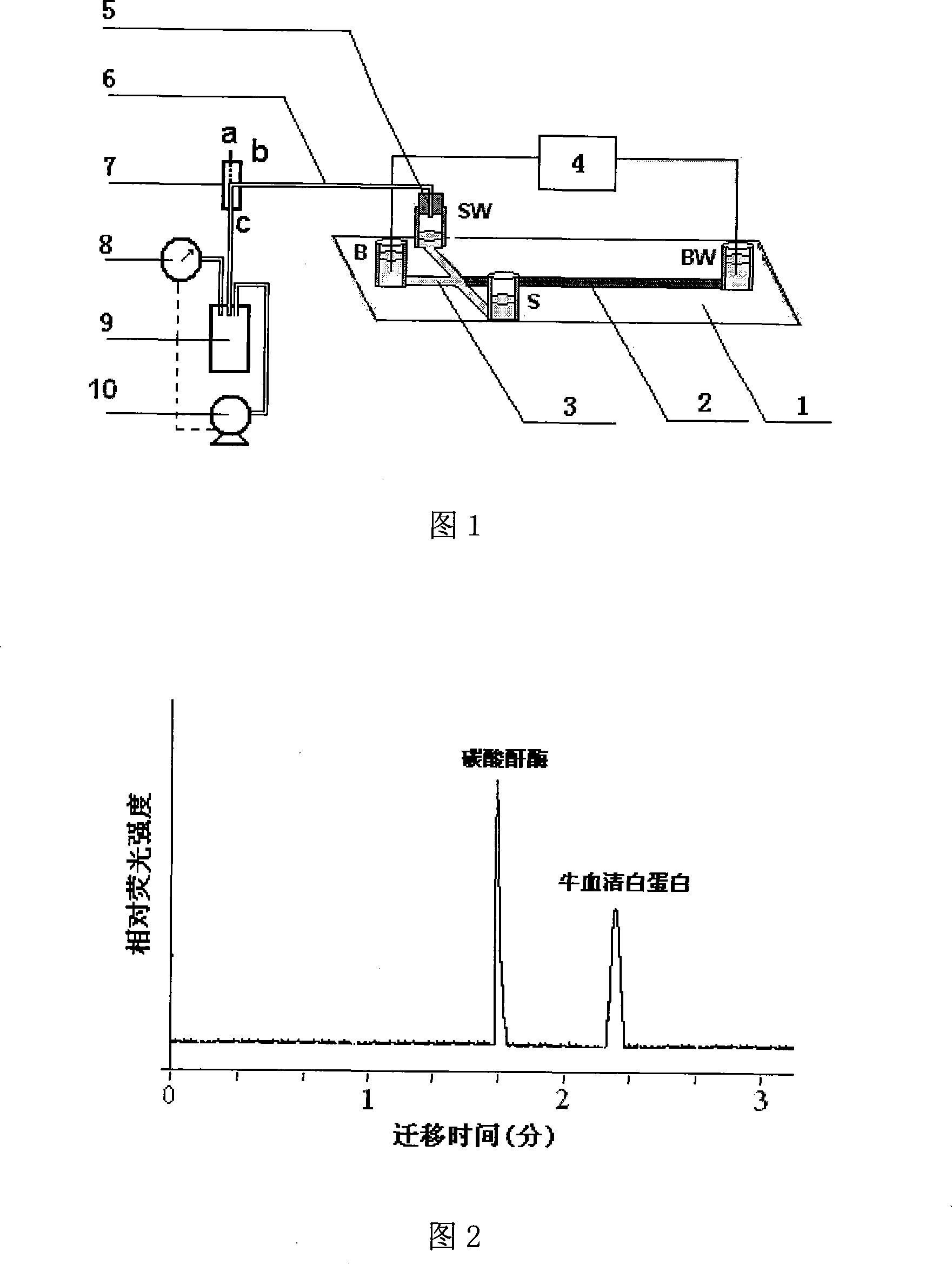
[0022] Referring to Fig. 1, the channel between the buffer pool (B) and the buffer waste pool (BW) on the microfluidic chip 1 is a separation channel (B-BW), and the sample liquid pool (S) and the sample waste pool ( The channel between SW) is the sampling channel S-SW. Add the sieving medium 2 to the buffer waste pool (BW), and fill the sieving medium 2 only in the separation channel from the buffer waste pool (BW) to the crossing of the channel, while the microfluidic chip The other channels, including the sampling channel (S-SW) and the separation channel between the buffer pool (B) and the channel crossing, are filled with electrophoresis buffer 3. Add the sample solution into the sample reservoir (S) on the microfluidic chip, add different volumes of electrophoresis buffer into the reservoir B and SW, and keep the height of the liquid level in the sample reservoir (S) lower than that of the buffer The height of the liquid level in the liquid pool (B), the height of the l...

Embodiment 2

[0026]According to Example 1, an example of separating different proteins by sieving electrophoresis on a microfluidic chip is provided. Referring to Figure 1, the width of the channel on the microfluidic chip is 60 μm, and the depth is 20 μm. The channel between S and SW is a sampling channel with a length of 10 mm, and the channel between B and BW is a separation channel with a length of 50 mm. The separation channel crosses the injection channel. Drill small holes at both ends of the sampling channel and the separation channel, and use adhesive to bond the micro plastic liquid storage tank on the small holes. The outer diameter of the plastic liquid storage tank is 6mm, the inner diameter is 4mm, and the height is 6mm. Use S, SW, B, and BW to represent the sample pool, sample waste pool, buffer pool, and buffer waste pool, respectively. Add 190 μL of sieving medium 12% linear polyacrylamide to the reservoir BW, and use a 20mL syringe to fill the 12% linear polyacrylamide i...

Embodiment 3

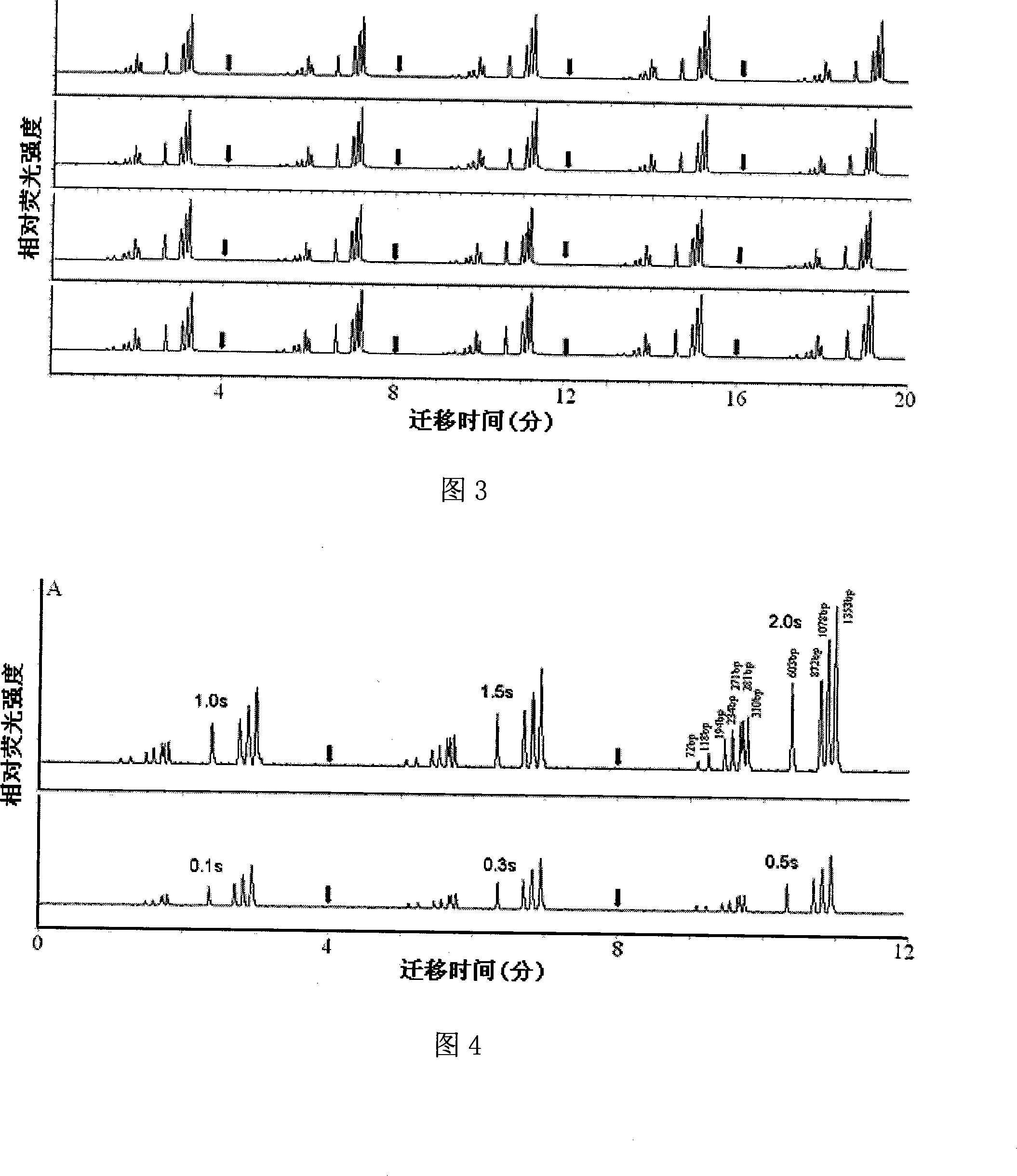
[0032] Another example of isolating DNA fragments is provided according to Example 1. The schematic diagram of the microfluidic chip sieving and electrophoretic separation device is shown in Figure 1, and the size of the microfluidic chip used is the same as that in Example 2. Use 2% hydroxyethyl cellulose as the sieving medium, use 1×TBE (90mmol / L Tris, 90mmol / L boric acid, 2mmol / L EDTA, pH8.2) as the electrophoresis buffer solution, and the DNA sample solution is fluorescent The concentration of reagent SYBR labeled is 5 μmol / L ΦX 174-hae III digest. Except that the separation voltage was adjusted from 1000V to 550V, other operating steps were the same as in Example 2. The electropherogram of the DNA sample analyzed 20 times with the injection time of 2 s is shown in Fig. 3 . It can be seen from Fig. 3 that the standard relative deviation of the DNA fragment migration time is 1.1-1.3%, and the standard relative deviation of the peak height is 5.0-9.0%. The electropherogra...


PUM


Abstract

A microfluidic chip sieving electrophoresis analytic method capable of controlling injection volume adopts a control device consisting of a microfluidic chip, a micro vacuum pump, a vacuum bottle, an electric contact vacuum meter, a three-way solenoid valve and a single high-voltage power supply. The method is characterized in that a sieving medium is filled in a separation channel between a buffer waster liquid tank (BW) and a channel cross intersection of the microfluidic chip; an electrophoretic buffer is filled the separation channel between other channels of the microfluidic chip, including an injection channel (S-SW) and a buffer tank (B), and the channel cross intersection; and two electrodes of the single high-voltage power supply are respectively with solution in the buffer tank (B) and the buffer waste liquid tank (BW) at both ends of the separation channel. The microfluidic chip sieving electrophoresis analytic method consists of injection and separation two stages. The injection volume can be adjusted arbitrarily through the duration time of the injection stage, and has the advantages of high injection speed, no discrimination effect, safe and reliable operation, low cost, etc.

Description

technical field [0001] The invention relates to a microfluidic chip sieving electrophoresis analysis technology, in particular to an analysis technique for changing the injection volume in the microfluidic chip sieving electrophoresis. Background technique [0002] Since the concept of micro-total analysis system was proposed in 1990, microfluidic chip technology has opened up a broad space for development in the fields of medicine and life sciences. Microfluidic chip sieving electrophoresis, which is filled with sieving media in microchannels, has been widely used to separate DNA fragments of different lengths and proteins of different molecular weights. [0003] In the microfluidic chip sieving electrophoresis analysis, due to the large fluid resistance after the sieving medium is filled in the microchannel, the electric pinch injection method is generally used to inject samples. That is, in the sample injection stage, a set of DC voltage is applied between the sample poo...

Claims


Application Information

Patent Timeline
IPC IPC(8): G01N27/447G01N35/08B01D57/02
Inventor 殷学锋戚丽雅张磊
Owner ZHEJIANG UNIV
Why Eureka
Try Eureka